High pressure dry coal slurry extrusion pump

a dry coal slurry and extrusion pump technology, which is applied in the direction of lighting and heating apparatus, charge manipulation, furnaces, etc., can solve the problems of reducing the efficiency of the reactor, difficult to pressurize to the high pressure needed for combustion, and many inefficiencies in the system

Inactive Publication Date: 2010-05-18
THE BOEING CO +1
View PDF20 Cites 45 Cited by
  • Summary
  • Abstract
  • Description
  • Claims
  • Application Information

AI Technical Summary

Problems solved by technology

Coal, even when highly pulverized, is substantially a solid material and difficult to pressurize to the high pressures needed for combustion.
Various systems have been developed to provide the high pressure coal required, but these systems all have numerous inefficiencies.
The carrier fluid of the slurry is also provided to the reactor as a large surplus in the slurry, thereby decreasing the efficiency of the reactor.
Still other systems have attempted to provide a feeder system which uses a screw feeder or pump, but has similar disadvantages.
These systems do not easily overcome the high pressure head against which the coal is pumped.
Like those which use incompressible fluids (i.e., water and carbon dioxide, CO2), these later pumps are also very complex and costly.

Method used


Image

  • High pressure dry coal slurry extrusion pump
  • High pressure dry coal slurry extrusion pump
  • High pressure dry coal slurry extrusion pump

Examples


example

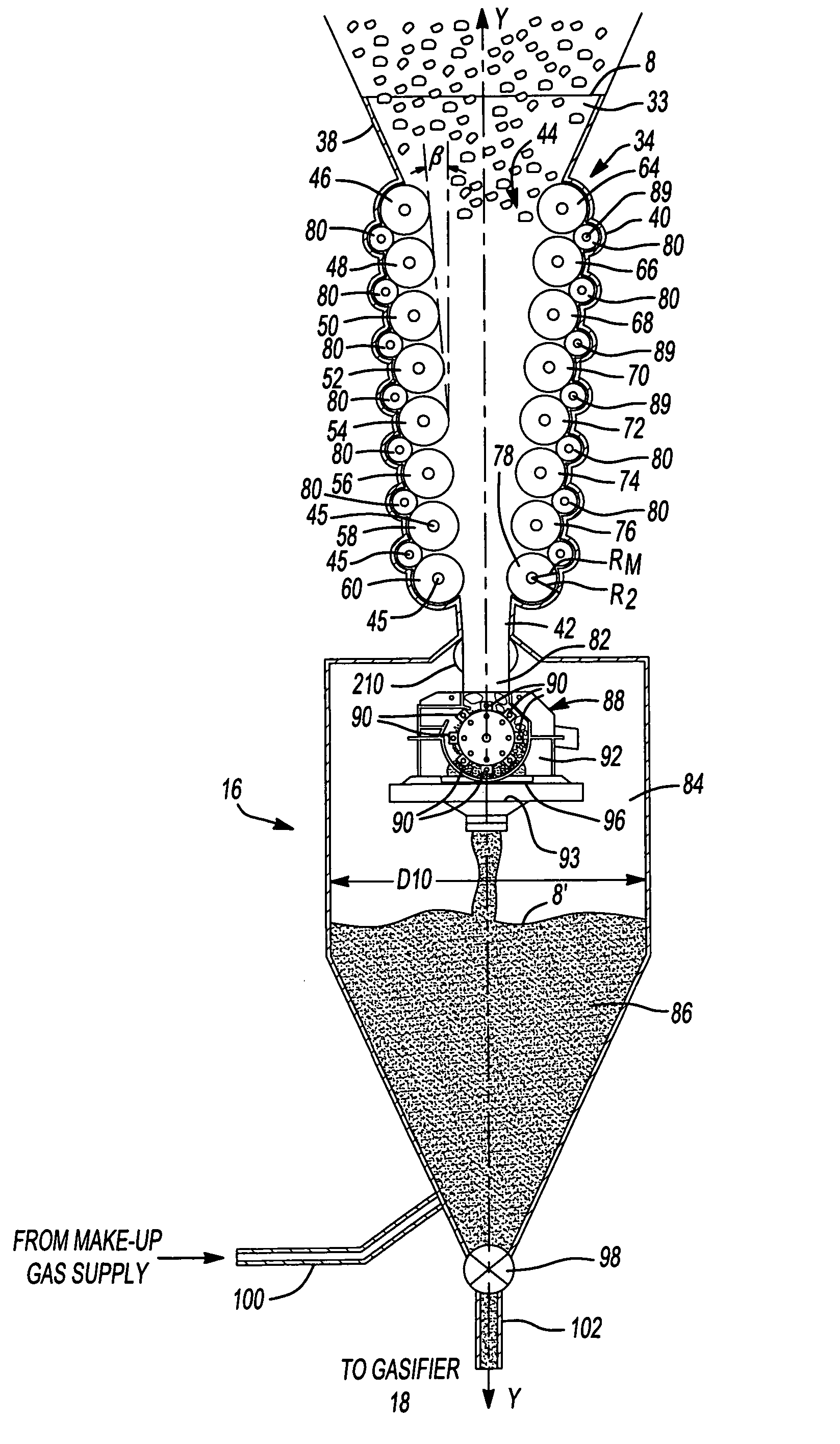
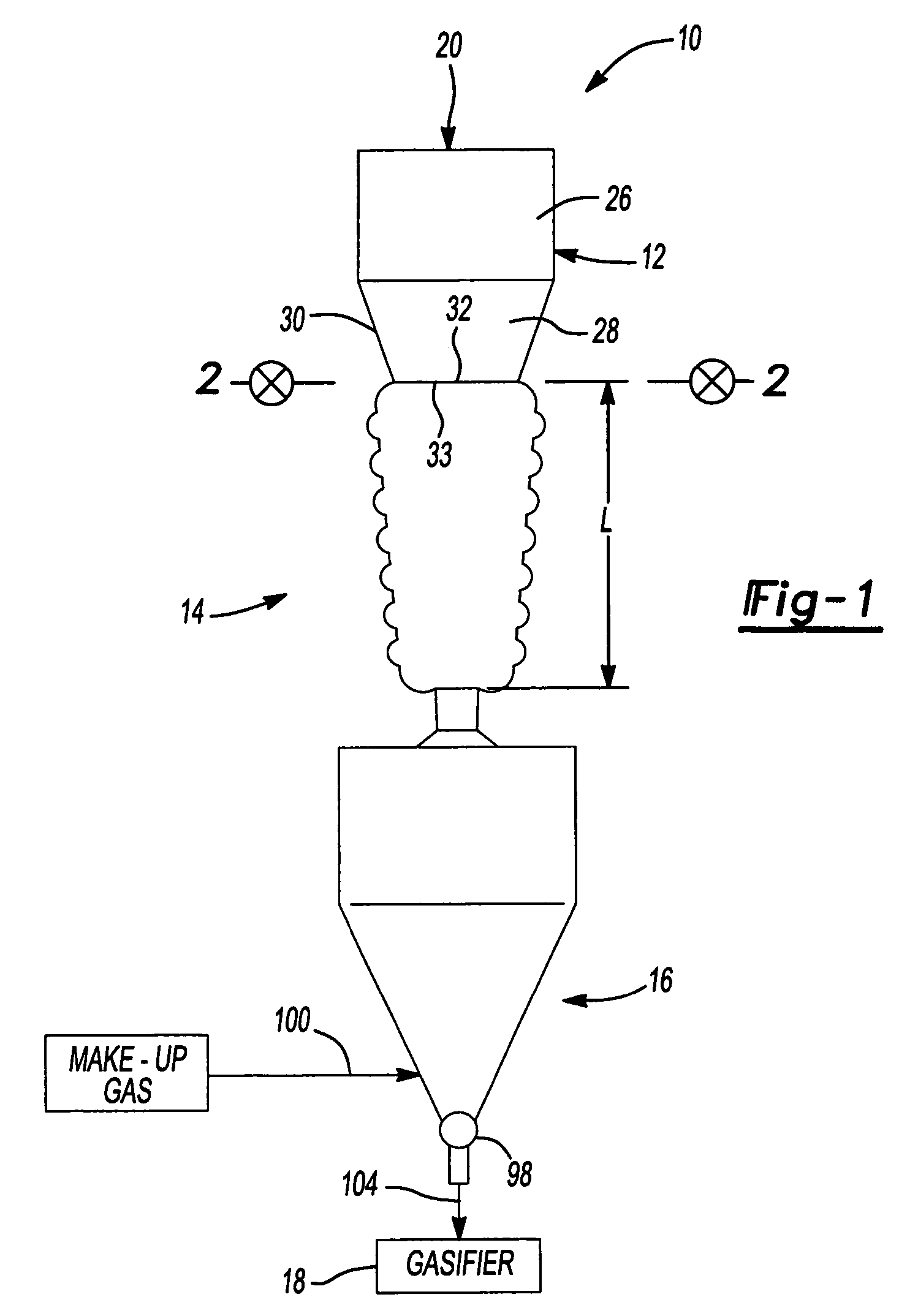
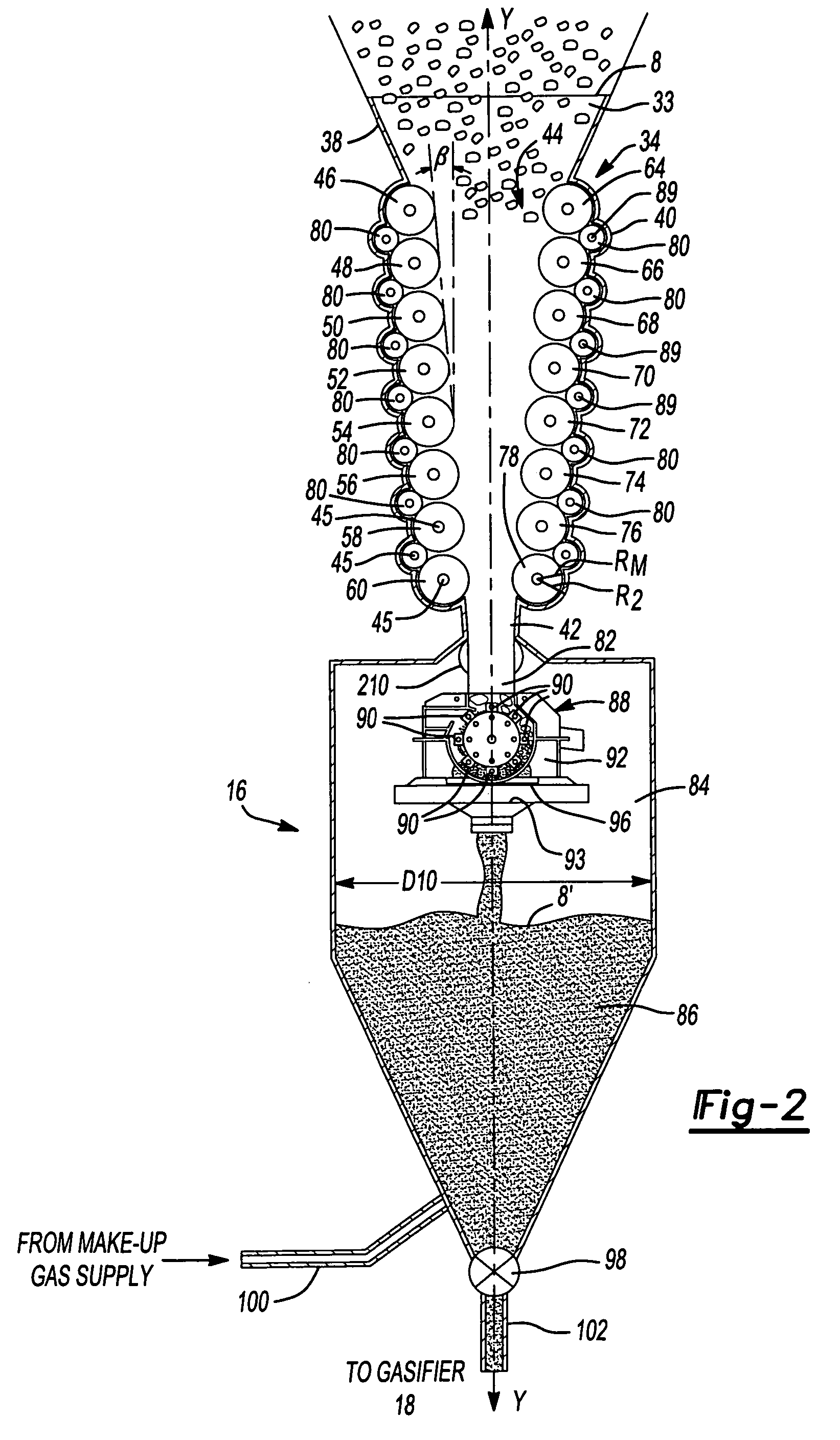
[0052]As an example of the various embodiments, consider the storage vessel 12 as containing coal to feed into the extruder pump 14. The coal may be assumed to have the following parameters:

[0053]

True Solids Density, ρs87.0 lb / ft3 (1,393 kg / m3)Initial Static Bed Void Fraction, εo0.570Solids / Wall Friction Angle, δw15 degreesSolids Compressibility Factor, κ3.28 × 10⁻³ inchessquared per poundforce (in2 / lbf) or 0.477inverse mega-Pascals(MPa−1)Mean Solids Particle Diameter, Dp28 micrometers (μm)(1.1 × 10⁻³ inches)

[0054]In this example, the coal may be transported using carbon dioxide gas having a dynamic viscosity within the upstream static bed of 0.0144 centipoises (ambient temperature and pressure state conditions of 80 degrees F. and 1 atmosphere) (0.0144 millipascal second).

[0055]From Equation 1, it can be shown that an extruder pump 14 having the plurality of motive rollers 44 with a total length w of 1.86 feet (ft) (0.567 meter (m)), an initial separation distance ho (D1) of 0.5 ft...


PUM

PropertyMeasurementUnit
angleaaaaaaaaaa
sizesaaaaaaaaaa
speedaaaaaaaaaa

Abstract

A system for providing highly pressurized raw fuel to a pressure reactor. The system includes an inlet for receiving the raw fuel and a roller system communicating with the inlet. The roller system includes a plurality of independent rollers arranged in two converging planes. The rollers of the roller system successively compress the raw fuel as the raw fuel passes through the roller system between the rollers, such that the fuel is highly pressurized when it reaches an output end of the roller system. An outlet is located adjacent the output end of the roller system to dispense the pressurized raw fuel to the pressure reactor.

Description

CROSS-REFERENCE TO RELATED APPLICATIONS[0001]The present application is related in general subject matter to U.S. Patent Application Publication No. 2004 / 0071618, entitled “Method and Apparatus for Continuously Feeding and Pressurizing a Solid Material into a High Pressure System,” filed Oct. 15, 2003, assigned to The Boeing Company, and hereby incorporated by reference into the present application. The subject matter of the present application is also related to U.S. patent application Ser. No. 10 / 677,817, entitled “Regeneratively Cooled Synthesis Gas Generator,” filed Oct. 2, 2003, presently allowed, the disclosure of which is also hereby incorporated by reference. Additionally, the subject matter of the present invention is related to U.S. patent application Ser. No. 11 / 081,144, entitled “Compact High Efficiency Gasifier,” filed Mar. 16, 2005. Finally, the subject matter of the present application is related to U.S. patent application Ser. No. 11 / 117,911, entitled “Advanced Coal ...

Claims


Application Information

Patent Timeline
Patent Type & Authority Patents(United States)
IPC IPC(8): F23K3/00
CPCB01J8/003B01J8/0045C10J3/50C21B11/08C21C7/0025F27D3/18C10J3/506C21B13/143B01J2208/00752C10J2300/093C10J2300/0906Y02P10/134
Inventor SPROUSE, KENNETH MMATTHEWS, DAVID R
Owner THE BOEING CO
Why Eureka
Try Eureka