Apparatus for controlling light emitting devices

a technology apparatuses, which is applied in the direction of electric variable regulation, process and machine control, instruments, etc., can solve the problems of insufficient output of under-lighted leds, insufficient temperature control of leds, and likely resistance changes in led illumination, so as to reduce the temperature effect of operating power, reduce unstable input voltage/current effects on operating power, and prolong the life of light emitting devices

Inactive Publication Date: 2010-05-18
L& C LIGHTING TECH
View PDF7 Cites 4 Cited by
  • Summary
  • Abstract
  • Description
  • Claims
  • Application Information

AI Technical Summary

Benefits of technology

[0007]In view of the foregoing, it is an object of the present invention to provide apparatus for controlling the LEDs, that is capable of reducing the temperature effects on the operating (or input) power of light emitting devices (such as LEDs), and reducing the unstable input voltage / current effects on the operating power of the light emitting devices. Accordingly, the present invention could protect and lengthen the life of the light emitting devices, stabilize the output illuminance of each light emitting device, and precisely mix the colors of the light emitting devices.

Problems solved by technology

The resistance of the interface (or node) between the N-type semiconductor and P-type semiconductor is susceptible to ambient temperature, and subsequently, the illuminance of the LED is likely to be affected by the resistance change.
Specifically, the varying ambient temperature may result in an over-heated and over-lighted LED with high output, or alternately may result in an under-lighted LED with insufficient output.
For example, in the constant-voltage driving mode when the ambient temperature rises, the interface resistance decreases, causing high operation power and heat for the LED and thus disadvantageously shortens the life of the LED; on the other hand, when the ambient temperature falls, the increased interface resistance causes low operating power for the LED, which renders the LED useless for its insufficient illuminance.
Alternatively, in the constant-current driving mode, when the ambient temperature rises, the decreased interface resistance causes low operating power of the LED, which renders the LED useless for insufficient illuminance; and when the ambient temperature falls, the increased interface resistance causes high operating power and heat of the LED, which disadvantageously shortens the life of the LED.
Further, the LEDs with different spectrums are susceptible to the ambient temperature with different degrees.
Accordingly, it is difficult to precisely arrive at a required color by mixing the different spectrums.

Method used


Image

  • Apparatus for controlling light emitting devices
  • Apparatus for controlling light emitting devices
  • Apparatus for controlling light emitting devices

Examples


Embodiment Construction

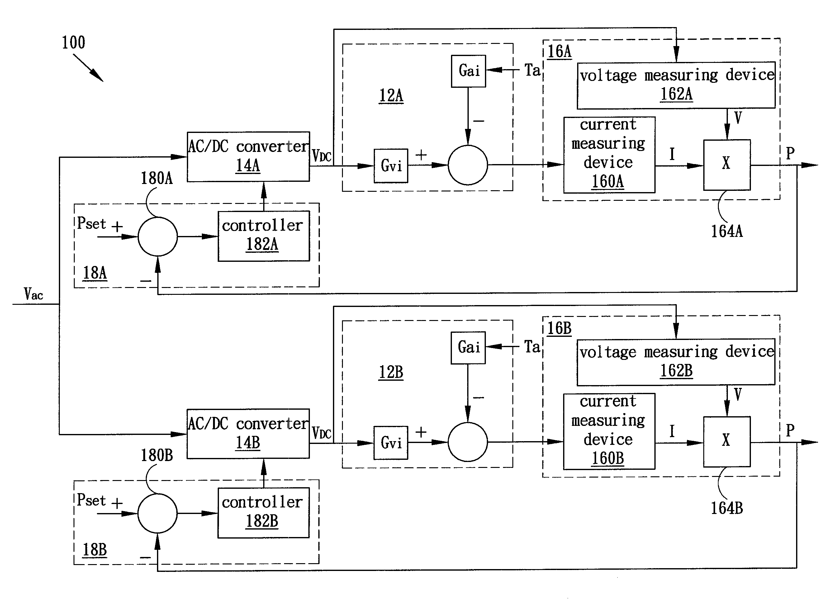
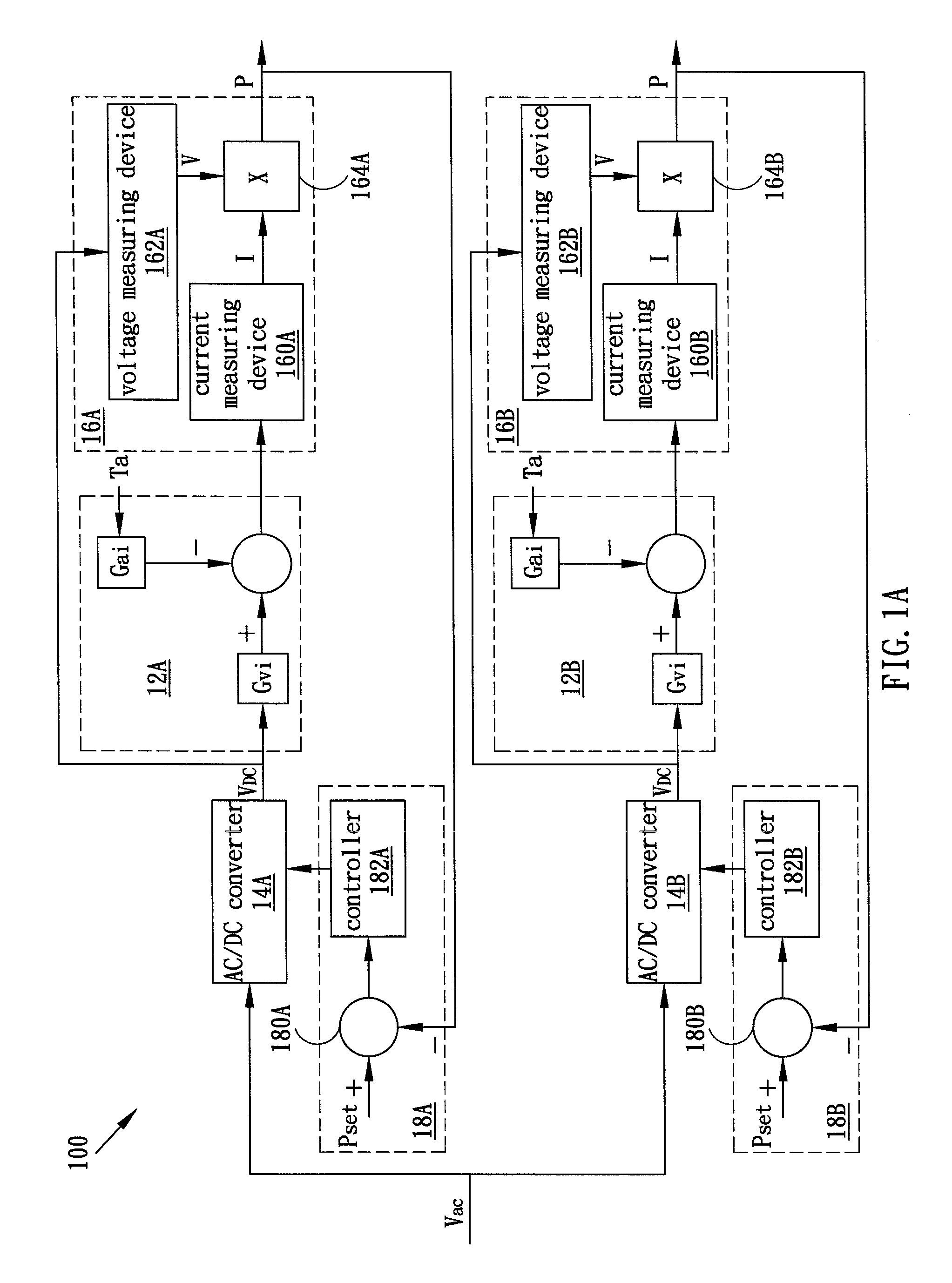
[0016]FIG. 1A shows an electrical connecting flow illustrating apparatus 100 for controlling light emitting devices according to one embodiment of the present invention. In the embodiment, the light emitting devices are light-emitting diodes (LEDs) 12A and 12B, which have different spectrums (or colors). More than two LEDs with at least two spectrums (or colors) may also be used. The output illuminance of the LED 12A and the LED 12B are independent, and can be controlled to mix optically to arrive at a specific color. For example, light from the LEDs with the three primary colors could be mixed to obtain different colors.

[0017]The LEDs 12A and 12B are influenced by input DC (i.e., direct current), voltage VDC and ambient temperature Ta. The equivalent circuits of the LEDs 12A and 12B are shown in the figure, in which gain Gvi represents the function between the current flowing through the LEDs (12A and 12B) and the input DC voltage, and gain Gai represents the function between the c...


PUM


Abstract

The present invention is related to the apparatus for driving the light emitting devices with different colors. The input powers of the light emitting devices are measured and controlled by a feedback control system to maintain constant, and by setting different power inputs to the different light emitting devices different stable colors are produced.

Description

BACKGROUND OF THE INVENTION[0001]1. Field of the Invention[0002]The present invention generally relates to apparatus for controlling light emitting devices, and more particularly to apparatus for driving light emitting diodes with different spectrums by a feedback control system to produce different stable colors.[0003]2. Description of the Prior Art[0004]For the advantages of less volume, less input power, longer life and lower cost, light-emitting diodes (LEDs) are replacing conventional lighting devices, and novel applications thereof are emerging. For example, various colors could be generated by independently controlling the illuminance (or intensity) of two (or more) LEDs with distinct spectrum (or color) and mixing the color optically.[0005]The LED is composed of N-type semiconductor and P-type semiconductor. The resistance of the interface (or node) between the N-type semiconductor and P-type semiconductor is susceptible to ambient temperature, and subsequently, the illumina...

Claims


Application Information

Patent Timeline
Patent Type & Authority Patents(United States)
IPC IPC(8): H05B37/02H05B44/00
CPCH05B33/086H05B45/20H05B45/28
Inventor HUANG, BIN-JUINETSENG, HENG-LUNYEH, JONG-FUHSU, PO-CHIENWU, MIN-SHENGCHEN, SHING-TUNGCHEN, KUO-YANG
Owner L& C LIGHTING TECH
Why Eureka
Try Eureka