Signal differentiation with differential conversion circuit

a conversion circuit and signal technology, applied in the field of circuits, can solve the problems of large required voltage isolation capacity, large volume of transformers, and large number of magnetic components in the package, and achieve the effects of preventing the saturation of transformers, eliminating frequency dependence between input signals, and preventing dc signal content from saturating magnetic components

Active Publication Date: 2010-05-18
LITTELFUSE INC
View PDF10 Cites 2 Cited by
  • Summary
  • Abstract
  • Description
  • Claims
  • Application Information

AI Technical Summary

Benefits of technology

[0007]Embodiments of the present invention use short-time (or short-pulse) duration signals and / or differential inputs to a transformer to prevent the saturation of the transformer. This enables the use of a significantly smaller-sized transformer than otherwise possible. The circuit transmits primarily the edge transition information from the input side of the transformer to the output side of the transformer. A differential signal is obtained at the output side of the transformer using the edge transition information. This eliminates the frequency dependence between the input signal and the signal transmission. The differential signal, converted from the input signal differentiation at the input side of the transformer, is read by a comparator on the output side of the transformer T1 to drive a power MOSFET or power IGBT in the present embodiment. In other embodiments, the differential signal may be used by other devices for other purposes.
[0008]A circuit according to present embodiments has one or more of the following advantages. The circuit eliminates the use of a coupling capacitor, thereby preventing DC signal content from saturating the magnetic component. The circuit minimizes magnetic size by using a differentiated signal with only high frequency content to extract transition information from a duty cycle modulated input signal. The circuit allows transmission of DC to MHz signals without significantly increasing the size of magnetic element, thus allowing the use of a small magnetic component that may be included in a packaged device.

Problems solved by technology

However, the required voltage isolation capacity tends to be very large in certain applications, e.g., 3750 volts or more, to protect against sudden spikes or fault conditions.
In the past, the transformer tended to be bulky and was placed external to a packaged gate driver.
However, the magnetic components included within the package would need to be significantly smaller than those used for the conventional transformers.

Method used


Image

  • Signal differentiation with differential conversion circuit
  • Signal differentiation with differential conversion circuit
  • Signal differentiation with differential conversion circuit

Examples


Embodiment Construction

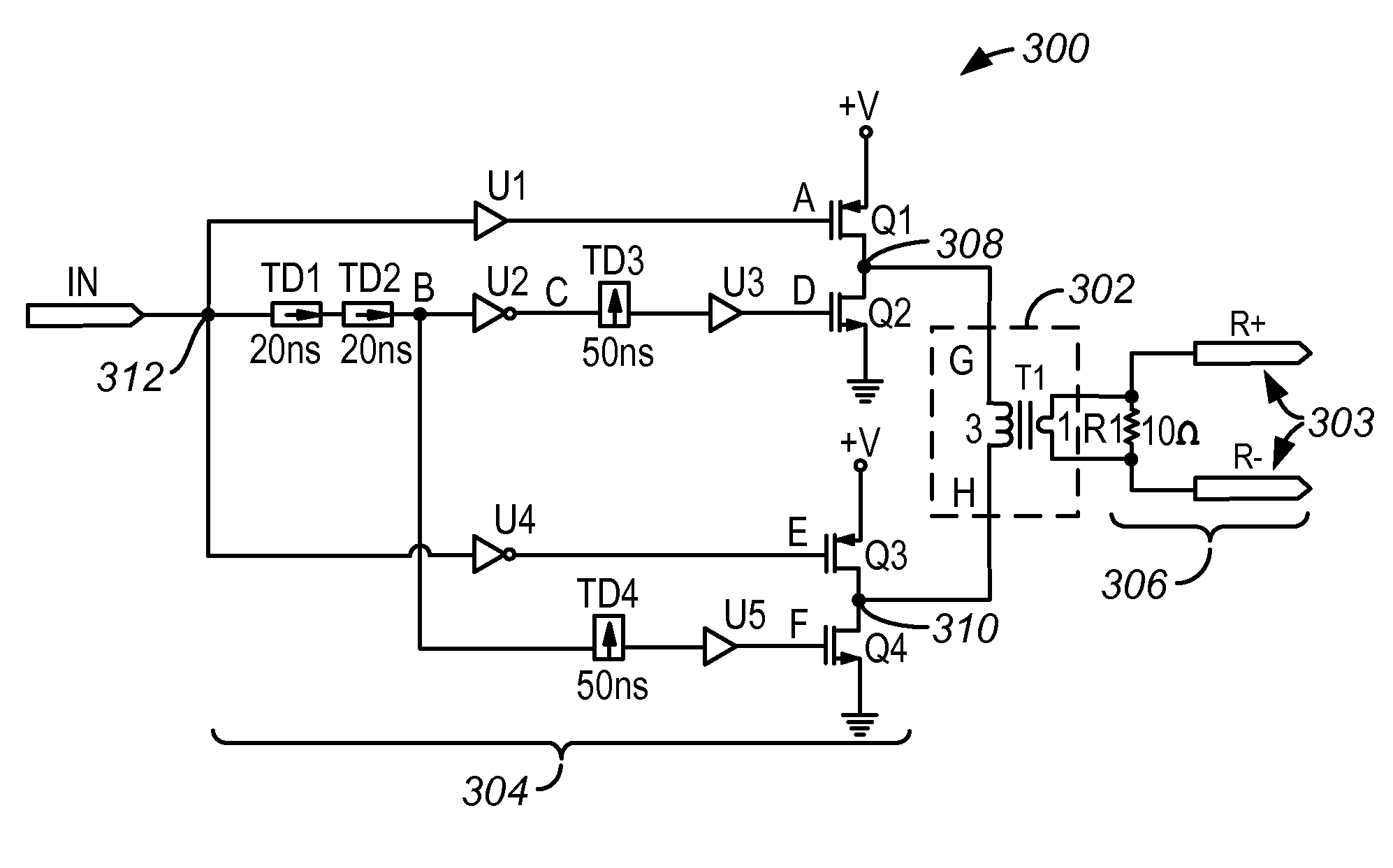
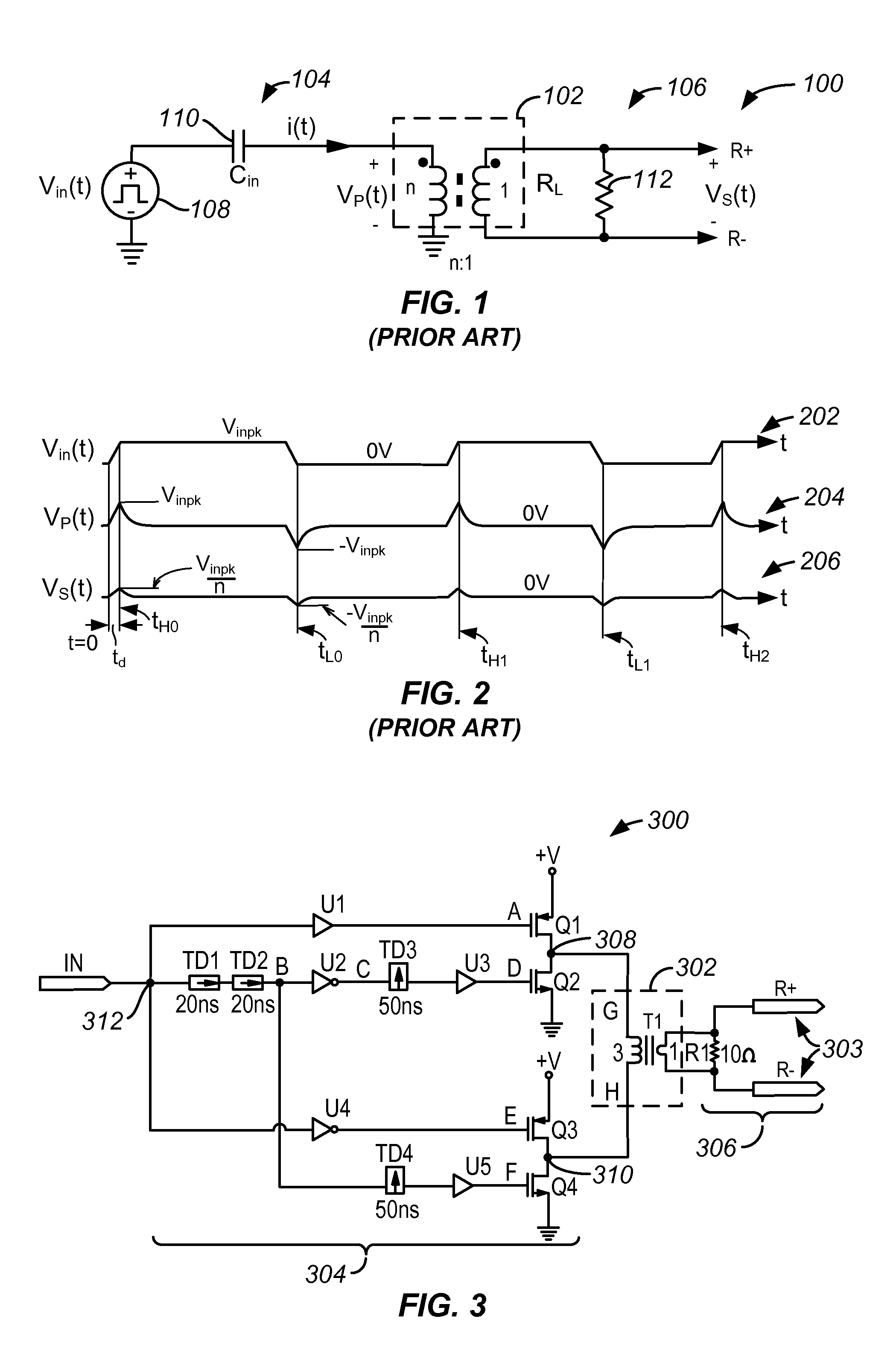
[0024]The present invention relates to a circuit for transmitting signals. The circuit is provided within a packaged device including a magnetic component in one embodiment. The present invention is illustrated in the context of a gate driver. However, the invention is not limited to such an application. The invention may be used to transmit various signals across a magnetic component, e.g., a transformer. In one embodiment, the circuit is used to transmit binary information using the pulse width and / or duty cycles of input signals.

[0025]Embodiments of the present invention use short-time (or short-pulse) duration signals and / or differential inputs to a transformer to prevent the saturation of the transformer. This enables the use of a significantly smaller-sized transformer than otherwise possible. The circuit transmits primarily the edge transition information from the input side of the transformer to the output side of the transformer. A differential signal is obtained at the out...


PUM


Abstract

A circuit for transmitting signals includes a transformer having an input side and an output side, the input side having a first end and a second end. A first transistor is coupled to the first end of the transformer, the first transistor being configured to provide a first signal to the first end in response to an input signal transitioning to a first state. A second transistor is coupled to the second end of the transformer; the second transistor being configured to provide a second signal to the second end in response to the input signal transitioning to a second state. The output side is configured to output differential signals according to the first and second signals applied to the transformer.

Description

CROSS-REFERENCES TO RELATED APPLICATIONS[0001]The present invention claims benefits of U.S. Provisional Application No. 60 / 776,029, filed on Feb. 22, 2006, which is incorporated by reference.BACKGROUND OF THE INVENTION[0002]The present invention relates to a circuit for transmitting signals across a magnetic boundary.[0003]Semiconductor power devices of various types are used in electronic and electrical devices to operate them. For example, power MOSFETs or IGBTs are used to supply power to such electronic or electrical devices. These power MOSFETs and IGBTs, in turn, are controlled by gate drivers that are coupled to the gates of the power MOSFETs and IGBTs.[0004]The potential difference between the input side and the output side is generally 3-20 volts. However, the required voltage isolation capacity tends to be very large in certain applications, e.g., 3750 volts or more, to protect against sudden spikes or fault conditions. Accordingly, the input side and the output side are i...

Claims


Application Information

Patent Timeline
Patent Type & Authority Patents(United States)
IPC IPC(8): H02M7/538
CPCH03K17/162H03K17/6872H03K17/284
Inventor OCHI, SAMHUMBERT, DON
Owner LITTELFUSE INC
Why Eureka
Try Eureka