Methods and apparatus for calibrating oscillators in a receiver

a receiver and oscillator technology, applied in the field of oscillator calibration, can solve the problems of significant frequency error in down-converted signals, lower accuracy of oscillators,

Active Publication Date: 2010-05-18
HARRIS GLOBAL COMM INC
View PDF25 Cites 3 Cited by
  • Summary
  • Abstract
  • Description
  • Claims
  • Application Information

AI Technical Summary

Problems solved by technology

The second oscillator has a lower accuracy than the first oscillator; consequently, the second down-conversion introduces significant frequency error into down-converted signals.

Method used


Image

  • Methods and apparatus for calibrating oscillators in a receiver
  • Methods and apparatus for calibrating oscillators in a receiver
  • Methods and apparatus for calibrating oscillators in a receiver

Examples


Embodiment Construction

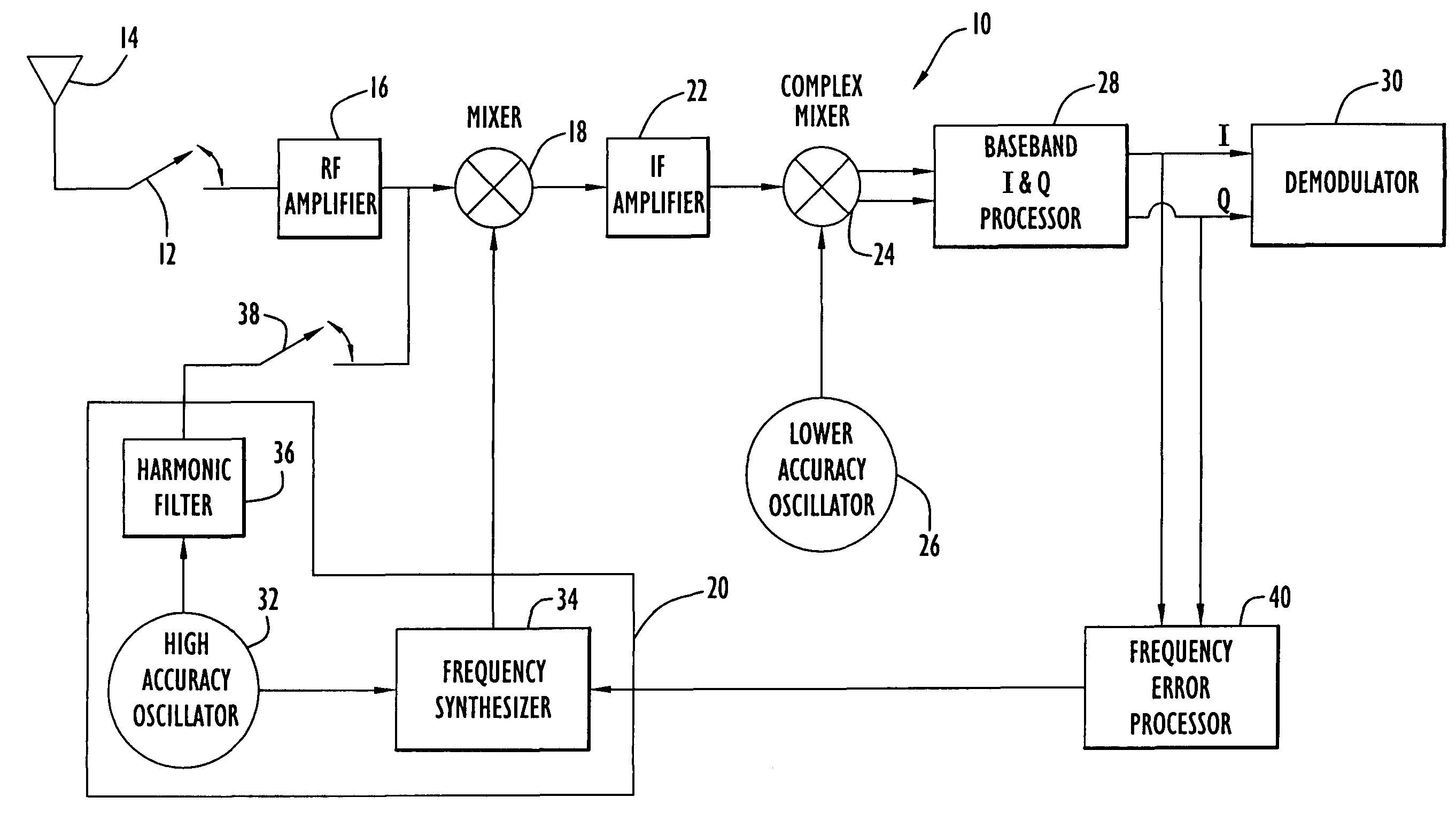
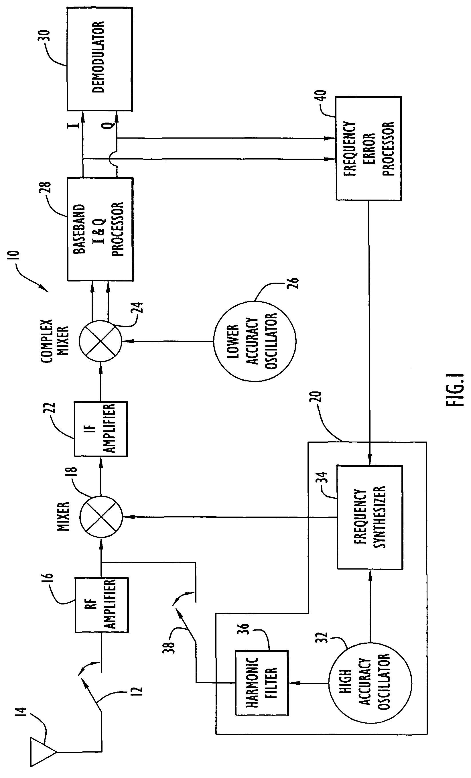
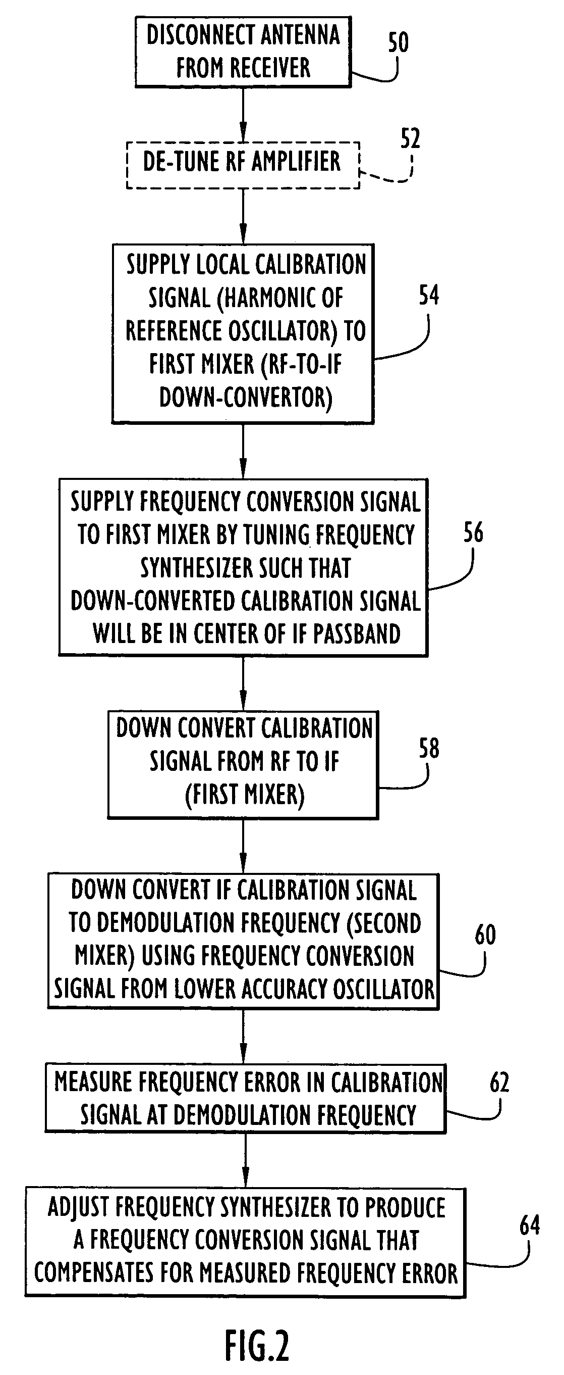
[0017]According to the invention, a harmonic of a signal generated by a high accuracy oscillator of a receiver can be used as a local calibration signal to correct for frequency errors caused by a lower accuracy oscillator operating in the receiver. The receiver can be calibrated to this known-frequency signal by measuring the frequency error present at the demodulator. With an I-Q type demodulator, the measured frequency error can be calculated by measuring the phase rotation versus time. This measured error can then be used to correct the tune frequency for all receiver channels. As described herein in greater detail, the techniques of the present invention can also be applied in other types of demodulators and the frequency error can be measured in different manners.

[0018]Referring to FIG. 1, a heterodyne receiver 10 having a single intermediate frequency (IF) is used to illustrate the concept of the invention. It will be understood, however, that the invention is not limited to ...


PUM


Abstract

A receiver includes a first oscillator supplying a reference frequency signal; a reference signal generator producing a first frequency conversion signal and a local calibration signal from the reference frequency signal; a first frequency converter responsive to the first frequency conversion signal to down-convert the received signal during normal receive operation and to down-convert the local calibration signal during calibration processing; a second frequency converter responsive to a second frequency conversion signal from a second oscillator to further down-convert the received signal and the local calibration signal; a demodulator that demodulates the received signal at a demodulation frequency; and a frequency error processor that determines a frequency error from the local calibration signal at the demodulation frequency, wherein the reference signal generator adjusts a frequency of the first frequency conversion signal used during normal receive operation in response to the frequency error to compensate for the frequency error.

Description

FIELD OF THE INVENTION[0001]This application relates to oscillator calibration, and more particularly, to methods and apparatus for calibrating one or more low accuracy oscillators using a high accuracy oscillator in RF receivers and the like.BACKGROUND[0002]Heterodyne types of radio receivers use multiple oscillator frequencies to convert incoming RF signals from the RF carrier frequency to a lower frequency at which demodulation is performed. In this process, the signal may be down-converted from RF to one or more intermediate frequencies (IFs) before being demodulated. The demodulation can be performed at an IF frequency (e.g., 455 kHz, 10.7 MHz, etc.) or at a baseband frequency using the I-Q complex representation of the signal. The overall receiver stability is a function of the sum of the stabilities of all oscillators used in the frequency conversions.[0003]Ideally, the conversion frequencies should be synthesized from a single, high-accuracy oscillator. However, this is not ...

Claims


Application Information

Patent Timeline
Patent Type & Authority Patents(United States)
IPC IPC(8): H04B1/18H03J1/00H04L27/00
CPCH03J1/0008H04L27/0014H03J2200/29H04L2027/0053H04L2027/0016H04L2027/0028H03D3/003H03D7/161
Inventor RODGERS, WILLIAM ELLISKWOLEK, RICHARD ALANWIGHT, BRUCE
Owner HARRIS GLOBAL COMM INC
Why Eureka
Try Eureka