Frequency conversion techniques using antiphase mixing

a technology of phase mixing and frequency conversion, applied in the direction of amplitude to angle modulation conversion, digital transmission, modulation, etc., can solve the problem of reducing the dynamic range available for the wanted baseband signal, generating spurious signals, and loss of signal-to-noise ratio (signal-to-noise ratio) from the da

Inactive Publication Date: 2008-02-26
ANDREW LLC
View PDF16 Cites 74 Cited by
  • Summary
  • Abstract
  • Description
  • Claims
  • Application Information

AI Technical Summary

Problems solved by technology

The main difficulty with direct upconversion is the generation of spurious signals that are often so close (spectrally) to the wanted signal that they cannot be removed by simple filtering at the modulator output. FIG. 2 shows typical spurious signals for the modulator of FIG. 1.
A significant problem with digital compensation of LO leakage is the loss of dynamic range (signal-to-noise ratio) from the DAC if the LO leakage signal 26 is too large.
This moves the origin of the baseband signal away from zero and reduces the dynamic range available for the wanted baseband signal.
Another problem with direct upconversion is distortion of the baseband signal, which results in spurious signals at the modulator output that are often too close (spectrally) to the wanted signal 25 to be easily removed by filtering after the modulator. FIG. 4 illustrates the appearance of three spurious signals 40, 42, and 44 in the vicinity of the wanted signal 25 due to second-order baseband distortion.
This distortion can be generated anywhere in the baseband circuit and is often produced in the DACs, the mixers, and baseband buffers (if any).

Method used


Image

  • Frequency conversion techniques using antiphase mixing
  • Frequency conversion techniques using antiphase mixing
  • Frequency conversion techniques using antiphase mixing

Examples


Embodiment Construction

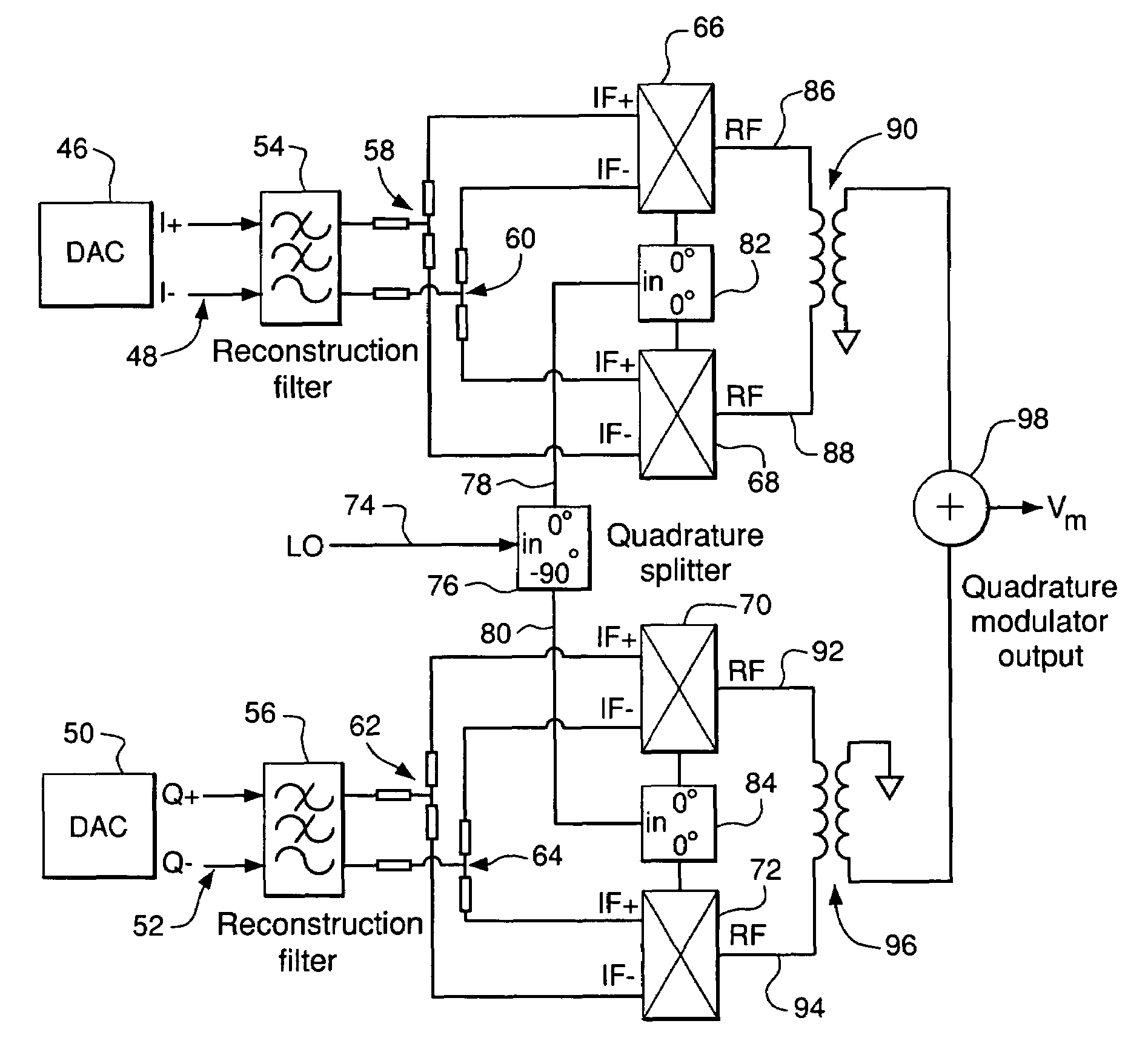
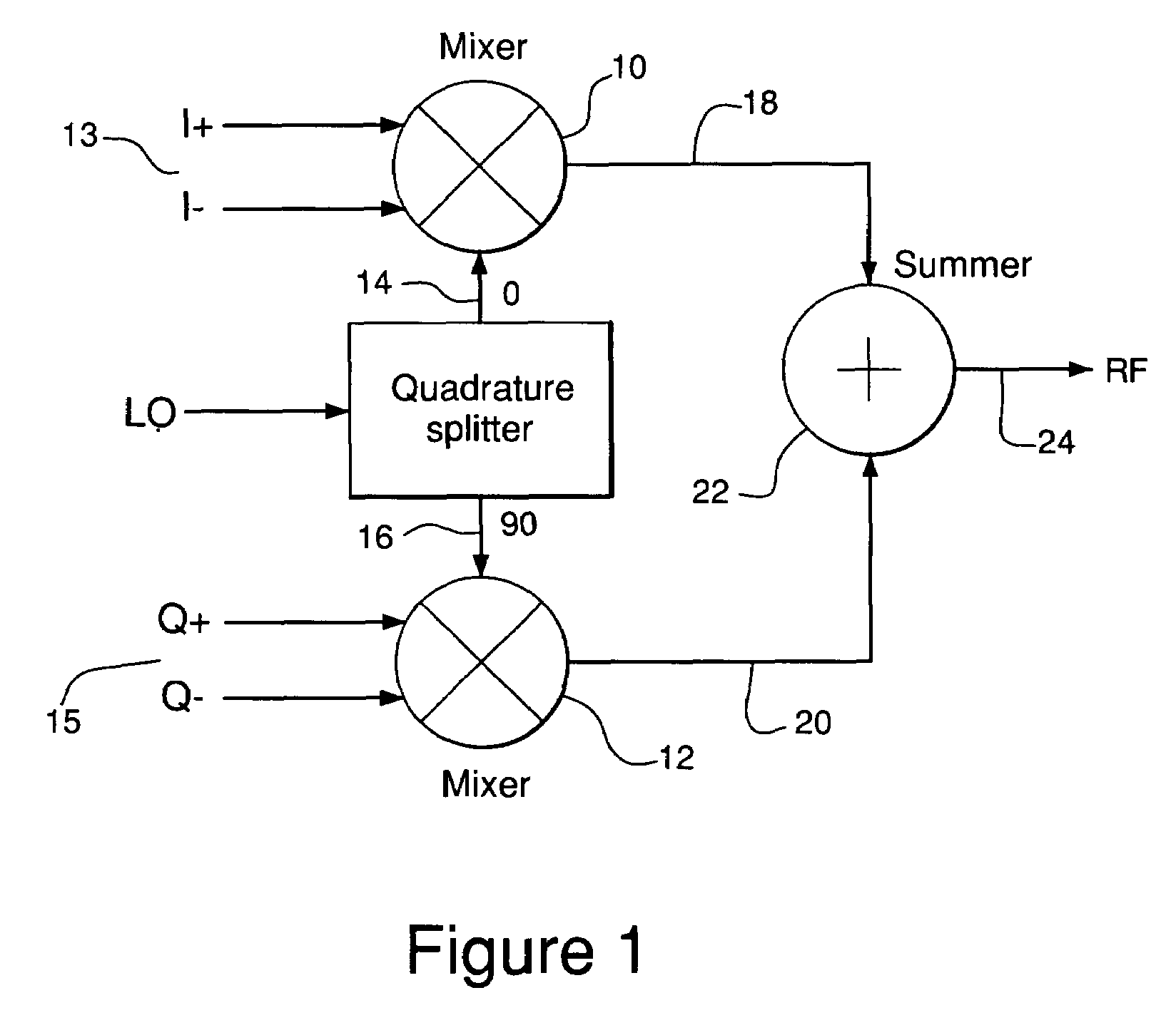
[0018]According to one aspect, the invention provides apparatus for frequency upconversion of a signal comprising two components, the apparatus comprising two pairs of mixers, each pair adapted to act on a respective one of the components and, in each pair, one mixer adapted to upconvert the component assigned to that pair and the other mixer adapted to upconvert an inverted version of that component; a pair of subtractors, each subtractor adapted to combine by subtraction the outputs of a respective one of the pairs of mixers; and a combiner adapted to combine the outputs of the subtractors to produce an upconverted version of the signal.

[0019]The invention also consists in a method of frequency upconversion of an input signal comprising two components, the method comprising a first upconverting step comprising mixing one of the components with a conversion signal to produce a first upconverted signal and mixing an inverted version of that component with the conversion signal to pr...


PUM


Abstract

A frequency upconverter using mixers operating on one or more signals and inverted versions thereof and a subtractor, such as a balun, for subtractively combining the mixer outputs to produce an upconverted signal.

Description

FIELD OF THE INVENTION[0001]The invention relates to frequency conversion processes, such as are used in radio communications systems.DESCRIPTION OF RELATED ART[0002]Information is exchanged in a radio communication system via a modulated radio frequency (RF) carrier wave. Typically, the modulating signal varies either the amplitude or the phase of the carrier wave (called AM and PM, respectively) although in modern communication systems both amplitude and phase are often varied simultaneously as in Quadrature Amplitude Modulation (QAM).[0003]A simple (and therefore cost-effective) way of generating a modulated carrier is by a process known as direct upconversion. Here, a baseband version of the modulated signal is translated from baseband to RF in a single step. In a modern radio communication system, the baseband modulated signal is normally generated digitally and converted into the analogue domain with the use of a digital-to-analogue converter (DAC). If the modulated signal has...

Claims


Application Information

Patent Timeline
Patent Type & Authority Patents(United States)
IPC IPC(8): H04B1/26H03C3/40
CPCH03C3/40
Inventor SMITHSON, ANTONY JAMES
Owner ANDREW LLC
Why Eureka
Try Eureka