Hollow anti-resonance optical fiber

An anti-resonance, optical fiber technology, applied in cladding fibers, light guides, optics, etc., can solve the problems of not having the complete bandgap characteristics of photonic crystal fibers, limiting application requirements, and narrow transmission bandwidth.

Inactive Publication Date: 2016-07-27
BEIJING UNIV OF TECH
View PDF6 Cites 73 Cited by
  • Summary
  • Abstract
  • Description
  • Claims
  • Application Information

AI Technical Summary

Problems solved by technology

In fact, due to the influence of roughness at the interface between silica and air, a strong coupling occurs between the fundamental mode in the core and the surface mode in the cladding, which not only leads to the fact that the lowest loss obtained experimentally for this type of fiber is only 1.2dB / km, which also affects the transmission performance of optical fibers, especially limiting the transmission of high-power lasers
On the other hand, the bandgap generation principle of the photonic bandgap hollow-core photonic crystal fiber determines that it has an inherent defect: the transmission bandwidth is narrow (difficult to exceed 70THz)
This means that the application of photonic bandgap hollow core photonic crystal fiber is limited to a very narrow spectral bandwidth range, which limits the application requirements in some applications requiring wide spectral bandwidth transmission.
[0004] The rise of HC-ARF research originated from the Kagome type optical fiber proposed by Professor Fetah Benabid of the University of Bath in 2002. Although its cladding is also periodically arranged air holes, it does not have the complete bandgap characteristics of photonic crystal fibers.

Method used


Image

  • Hollow anti-resonance optical fiber
  • Hollow anti-resonance optical fiber
  • Hollow anti-resonance optical fiber

Examples


Embodiment Construction

[0027] Specific embodiments of the present invention will be described in further detail below in conjunction with the accompanying drawings.

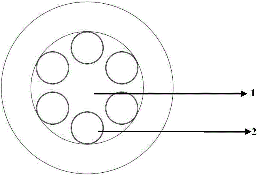
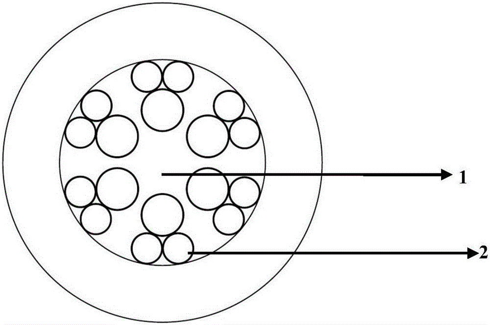
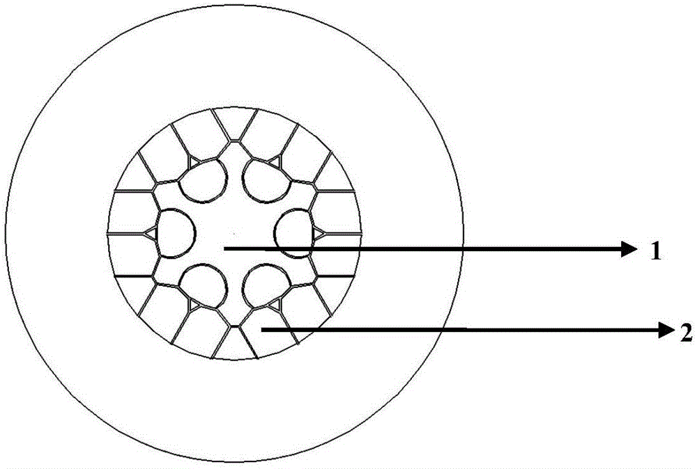
[0028] figure 1 , figure 2 with image 3 Schematic diagrams of end face structures of the first, second and third embodiments of the hollow-core anti-resonant optical fiber of the present invention are given. Their structures all include a core region (1) with a low refractive index and a cladding region with a high refractive index, and the cladding region with a high refractive index is jointly composed of an inner cladding region (2) and an outer cladding region. Among them, the low-refractive-index core area (1) is air; the inner cladding area (2) is formed by a plurality of microcapillaries, and the innermost (closest to the core) circle of microcapillaries is not in contact with each other and has no nodes. , has a negative curvature structure; the outer cladding region is formed by a solid material with a uniform distributio...


PUM


Abstract

The invention discloses a hollow anti-resonance optical fiber, and belongs to the technical field of optics and laser photoelectrons.The basic structure of the hollow anti-resonance optical fiber comprises a fiber core area with low refraction rate and a wrapping layer area with high refraction rate.The wrapping layer area with high refraction rate is divided into an inner wrapping layer region and an outer wrapping layer region.The inner wrapping layer region is composed of one or two layers of micro capillary pipes.The fiber core area with low refraction rate is wrapped by the inner wrapping layer region.Compared with a traditional band gap type hollow-core photonic crystal fiber, the hollow anti-resonance optical fiber has the advantages of being large in spectral bandwidth, small in bending loss, low in transmission loss, high in damage threshold and capable of keeping single-modulus transmission.A high-efficiency and high-sensitivity ideal platform is created for nonlinear frequency conversion, trace gas / liquid detection, high-power pulse compression and other foremost application.

Description

technical field [0001] The invention belongs to the technical field of optics and laser optoelectronics, and in particular relates to a hollow-core anti-resonant fiber (Hollow-core Anti-Resonant Fiber, HC-ARF) with a working wavelength and a nodeless structure. The invention also relates to methods of making HC-ARF. Background technique [0002] As a major research direction in fiber optics, hollow-core fibers have some remarkable advantages because they use the air in the core to guide light. Compared with solid-core fibers, hollow-core fibers utilize the ultra-low Rayleigh scattering and nonlinear coefficients of air (several orders of magnitude lower than all glass materials), and in principle can achieve ultra-low loss and low nonlinear optical transmission. In addition , can also provide higher propagation speeds (i.e., smaller delays) and laser damage thresholds. [0003] Among them, the photonic bandgap hollow-core photonic crystal fiber is inspired by the concept o...

Claims


Application Information

Patent Timeline
Patent Type & Authority Applications(China)
IPC IPC(8): G02B6/02
CPCG02B6/02304
Inventor 汪滢莹高寿飞刘小璐王璞
Owner BEIJING UNIV OF TECH
Why Eureka
Try Eureka