Analog signal processing circuit and communication device therewith

a signal processing circuit and analog signal technology, applied in the direction of transmission, electrical equipment, etc., can solve the problems of disadvantages such as power consumption, cost, implementation size, and disadvantages of providing a large number of analog signals for mobile radio units

Inactive Publication Date: 2007-03-22
KK TOSHIBA
View PDF8 Cites 79 Cited by
  • Summary
  • Abstract
  • Description
  • Claims
  • Application Information

AI Technical Summary

Benefits of technology

[0005] Recent wireless communications have been realized over a broadband network, and according to it advanced specifications have been required for ADCs. The power consumption and area for a high-speed and high-resolution ADC are very large, and providing a large number of ADCs for a mobile radio unit is disadvantageous in power consumption, implementation size, and cost. Therefore, in a multi-mode and multi-band receiver normally requiring a large number of ADCs, it is very effective means for realizing a small, low cost, and low power consumption system to reduce the number of ADCs.

Problems solved by technology

Therefore, to attain the use above, it is an important and imminent problem to realize a small and low power-consumption multi-band and multi-mode terminal capable of simultaneously receiving radio signals of a plurality of standards, but a multi-mode and multi-band receiver normally requires a large number of analog-to-digital converters (hereinafter referred to as an ADC).
The power consumption and area for a high-speed and high-resolution ADC are very large, and providing a large number of ADCs for a mobile radio unit is disadvantageous in power consumption, implementation size, and cost.

Method used


Image

  • Analog signal processing circuit and communication device therewith
  • Analog signal processing circuit and communication device therewith
  • Analog signal processing circuit and communication device therewith

Examples


first embodiment

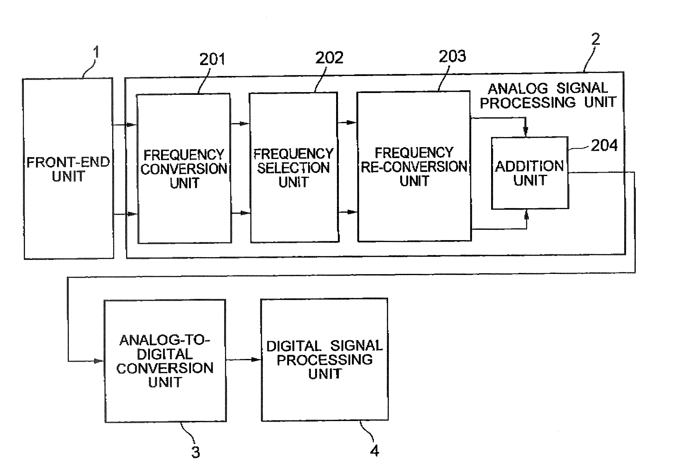
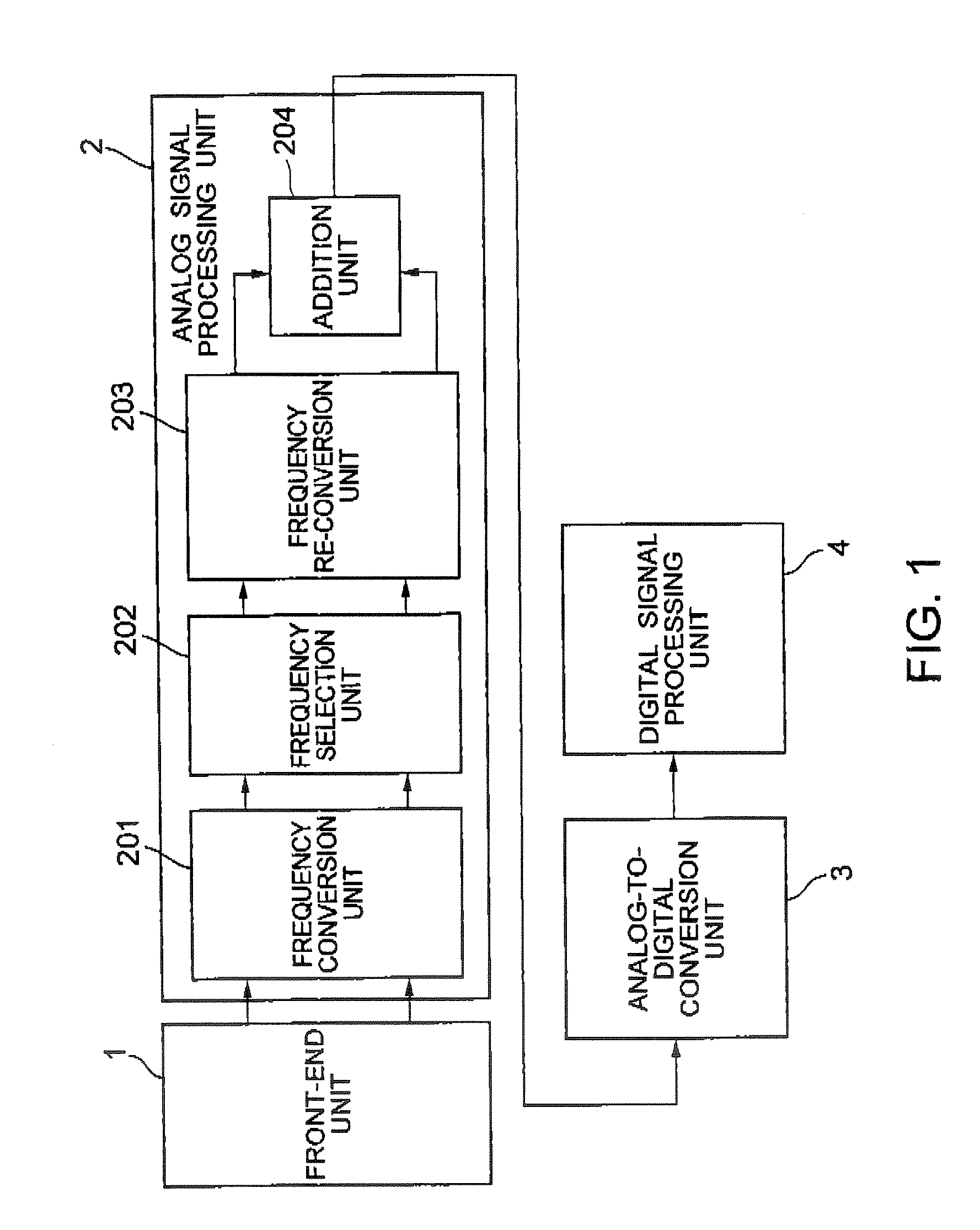
[0023]FIG. 1 is a block diagram of the communication device according to a first embodiment of the present invention, and receives a plurality of different radio signals (hereinafter referred to as RF (radio frequency) signals). Different RF signals means that each RF signals have different center frequencies each other, or, the same center frequencies but different amplitude-characteristics or phase-characteristics each other. FIG. 1 shows simultaneously receiving two different RF signals.

[0024] The communication device according to the present embodiment has a front-end unit 1 for receiving a plurality of different RF signals, an analog signal processing unit 2 for converting the received RF signals to a desired frequency band and combining them, an analog-to-digital conversion unit 3 for converting the analog signals combined by the analog signal processing unit 2 to digital signals, and a digital signal processing unit 4 for separating the combined digital signals in the digita...

second embodiment

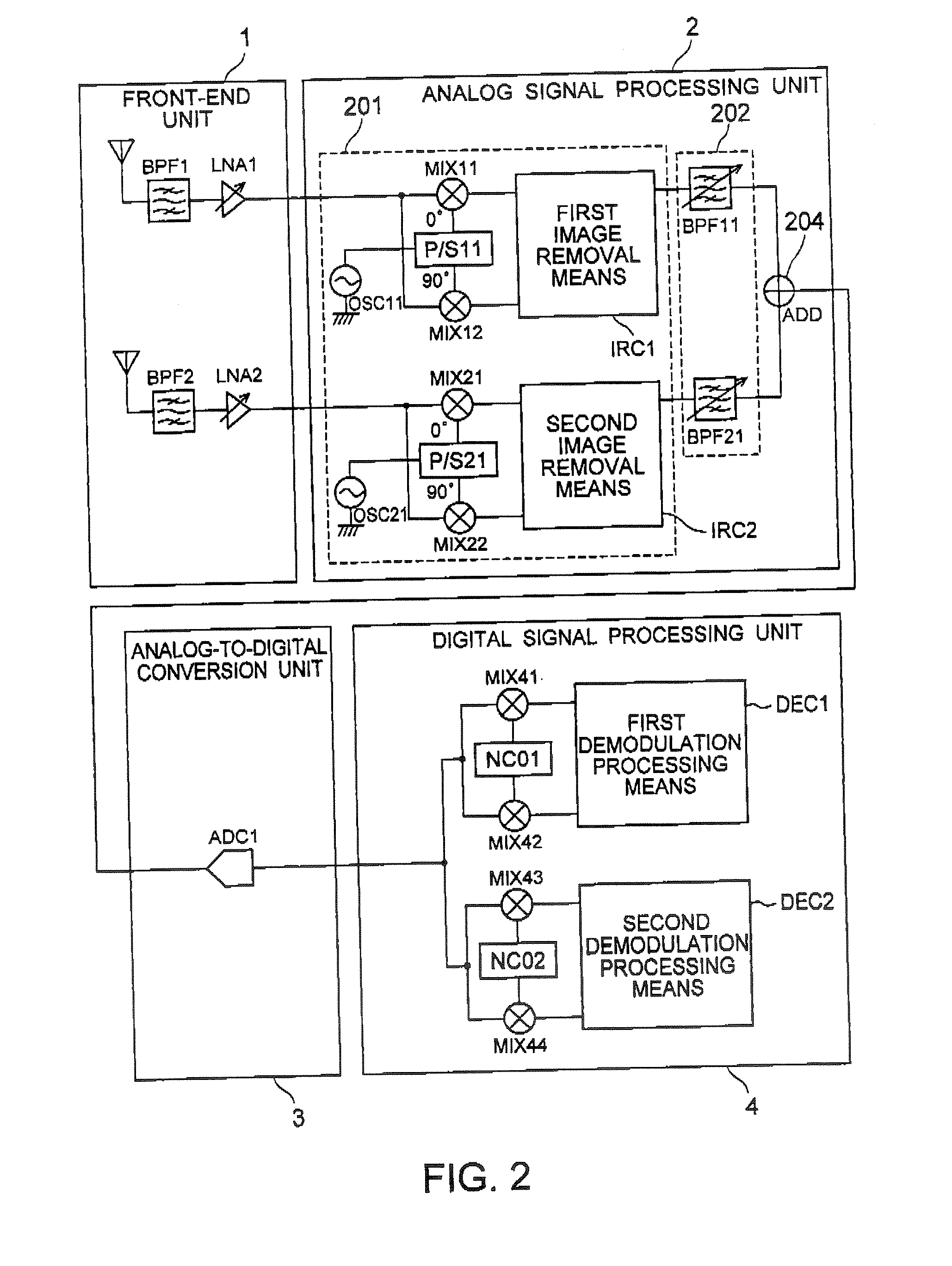
[0035]FIG. 2 is a block diagram of the communication device according to the second embodiment of the present invention, and shows a radio receiver in a multi-band and multi-mode by the Low-IF system. The Low-IF system is a system of down converting the center frequency of an RF signal to the frequency between a half of the RF signal's band widths and several times of it. The same components shown in FIG. 1 are assigned the same reference numerals, and the explanation is omitted here, The different portions are explained below.

[0036] The front-end unit 1 has an antenna, a bandpass filter BPF, and a low noise amplifier LNA for a plurality of received RF signals. In the present embodiment, the front-end unit 1 has pairs of components, that is, an antenna 1 and an antenna 2, bandpass filters BPF 1 and BPF 2, and low noise amplifiers LNA 1 and LNA 2.

[0037] The antenna 1, the BPF 1, and the LNA 1 are connected in this order, and the received RF signal is transmitted first to the antenn...

third embodiment

[0061]FIG. 4 is a block diagram of the third embodiment of the present invention.

[0062] The present embodiment with an analog signal processing unit uses a direct conversion system in which it is not necessary to reject an image, temporarily down converts a center frequency of a signal to a direct current signal (hereinafter referred to as a DC) and selects a channel at the B / B (baseband), adds up-converted signals after channel selection, and then outputs the result to the analog-to-digital conversion unit. The channel selection refers to selecting a desired channel from a plurality of channels in the signal band and rejecting other channels.

[0063] In FIG. 4, the components also shown in FIGS. 1 and 2 are assigned the same reference numerals, and the explanation of the components is omitted, and only the differences are explained here. Thus, by directly down converting to a baseband signal, an unnecessary frequency component (image) does not occur. Therefore, in the present embod...


PUM


Abstract

An analog signal processing circuit including: a frequency conversion unit for receiving a plurality of radio frequency signals having different center frequencies or a plurality of radio frequency signals having the same center frequencies but different amplitude-characteristics or phase-characteristics and converting the frequencies of the signals; a frequency selection unit for selecting a signal output from the frequency conversion unit at a predetermined band width; and an addition unit for adding a plurality of signals output from the frequency selection unit is provided.

Description

CROSS REFERENCE TO RELATED APPLICATIONS [0001] This application is based upon and claims the benefit of priority from the prior Japanese Patent Application No. 2005-270300, filed on Sep. 16, 2005, the entire contents of which are incorporated herein by reference. BACKROUND OF THE INVENTION [0002] The present invention relates to communication equipment, and more specifically to a communication device having an analog signal processing circuit capable of simultaneously receiving signals of a plurality of standards. [0003] Recently, a demand for multi-band and multi-mode system has increased. Only one wireless standard is not appropriate for all wireless applications, but various wireless standards such as a mobile telephone, a broadcast, a wireless LAN, a wireless PAN, etc. are used depending on each use. It is easily anticipated that a user will be able to use one mobile terminal to retrieve information by WEB browsing via a wireless LAN while enjoying a digital television broadcast...

Claims


Application Information

Patent Timeline
Patent Type & Authority Applications(United States)
IPC IPC(8): H04B1/18
CPCH04B1/0014H04B1/28H04B1/0032
Inventor TSUCHIE, KOJIHAMADA, MOTOTSUGUNAMEKATA, MINORUUNEKAWA, YASUO
Owner KK TOSHIBA
Why Eureka
Try Eureka