Software interface mapping tool

a software interface and mapping technology, applied in the field of software interface mapping tools, can solve the problems of large number of man hours needed to create and maintain the repository, no effective way to determine how future changes or additions will impact the system, and rapid abandonmen

Inactive Publication Date: 2010-05-18
SPRINT CORPORATION
View PDF11 Cites 9 Cited by
  • Summary
  • Abstract
  • Description
  • Claims
  • Application Information

AI Technical Summary

Problems solved by technology

If no documentation is created then there is no effective way to determine how future changes or additions will impact the system.
In the past there have been efforts to manually create metadata repositories for documenting the structure and changes made in a system; however, they were quickly abandoned due to a number of reasons.
One reason for abandonment was the large number of man hours needed to create and maintain the repository.
This problem is further exacerbated in an enterprise where multiple systems are communicating with each other.
Still further complexity is added since as an enterprise grows and changes, legacy systems within the enterprise might not present data in a useful way for newer systems that are created.
Further, since there are more changes occurring across an enterprise than just within a single system, there are more people responsible for updating the repository and there is a greater chance that updates to the repository won't be made, causing the repository's utility to be reduced due to the data's lack of integrity.
As such, it has not been feasible to create and maintain such a repository to date.

Method used


Image

  • Software interface mapping tool
  • Software interface mapping tool
  • Software interface mapping tool

Examples


Embodiment Construction

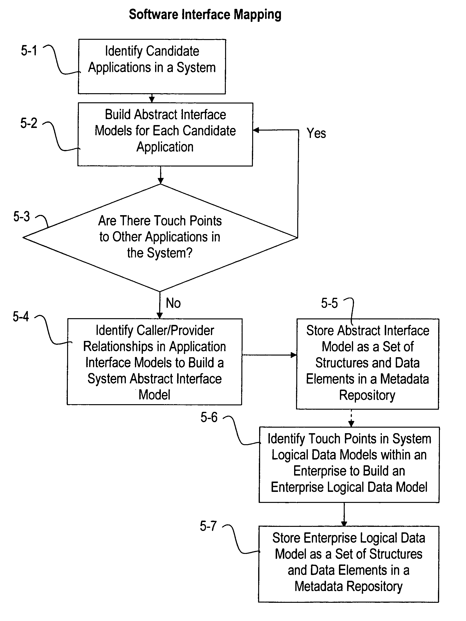
[0021]Disclosed hereinbelow is a method for documenting caller / provider relationships, data structures, and data transformations as an abstract interface model in a system or across multiple systems in an enterprise in an automated fashion or with minimal user input. This is accomplished by identifying caller / provider touch points between applications in a system and between systems in an enterprise. Once the caller / provider touch points have been identified for a system, a system logical data model may be created and stored as a set of structures and data elements in a metadata repository. The process of creating a system logical data model can be repeated for each system in an enterprise to create an enterprise logical data model which can similarly be stored as a set of structures and data elements in a metadata repository. This method of creating a system logical data model or an enterprise logical data model enables the creation of a metadata repository that is accurate, easily...


PUM


Abstract

Disclosed herein is an automated software interface mapping tool for determining and documenting caller / provider relationships, data structures, and data transformations as a system logical data model of a single system or across multiple systems in an enterprise. The system logical data model may be stored as a set of structures and data elements in a metadata repository. The metadata repository enables improved impact analysis, documents dependencies, serves as a tool for implementing application rationalization, and aids in the creation of future code for the generation of new applications or systems.

Description

CROSS-REFERENCE TO RELATED APPLICATIONS[0001]None.STATEMENT REGARDING FEDERALLY SPONSORED RESEARCH DEVELOPMENT[0002]Not applicable.REFERENCE TO A MICROFICHE APPENDIX[0003]Not applicable.BACKGROUND OF THE INVENTION[0004]As software systems are created they implement a complex web of caller / provider relationships between various applications and data sources. As changes are made in a system it is presently left to the people who made those changes to properly document how the system has been changed. If no documentation is created then there is no effective way to determine how future changes or additions will impact the system. In the past there have been efforts to manually create metadata repositories for documenting the structure and changes made in a system; however, they were quickly abandoned due to a number of reasons. One reason for abandonment was the large number of man hours needed to create and maintain the repository. Another reason was the fact that the integrity of the...

Claims


Application Information

Patent Timeline
Patent Type & Authority Patents(United States)
IPC IPC(8): G06F17/30G06F15/16
CPCG06Q10/10
Inventor BIERE, DEVON LMICKLAVZINA, CHARLES L.
Owner SPRINT CORPORATION
Why Eureka
Try Eureka