[0015]One aspect of the present invention provides an integrally formed glove having a unitary body that has sufficient length to protect the hand and arm of the user. The arm portion of the glove is below the wrist portion of the glove and is generally tapered with the diameter of the glove at the arm portion gradually increases to accommodate the arm of the user comfortably. This is called out here as the arm portion rather than a cuff portion since the arm portion is expected to be longer in length and comprises features that enable the formation of a liquid capturing trough. The portion of the glove below the trough is hereby termed as the cuff portion of the glove. The glove has nearly uniform latex wall thickness with predictable stretching properties. The glove can be manufactured by dipping a coagulant treated shaped glove former in a latex emulsion.
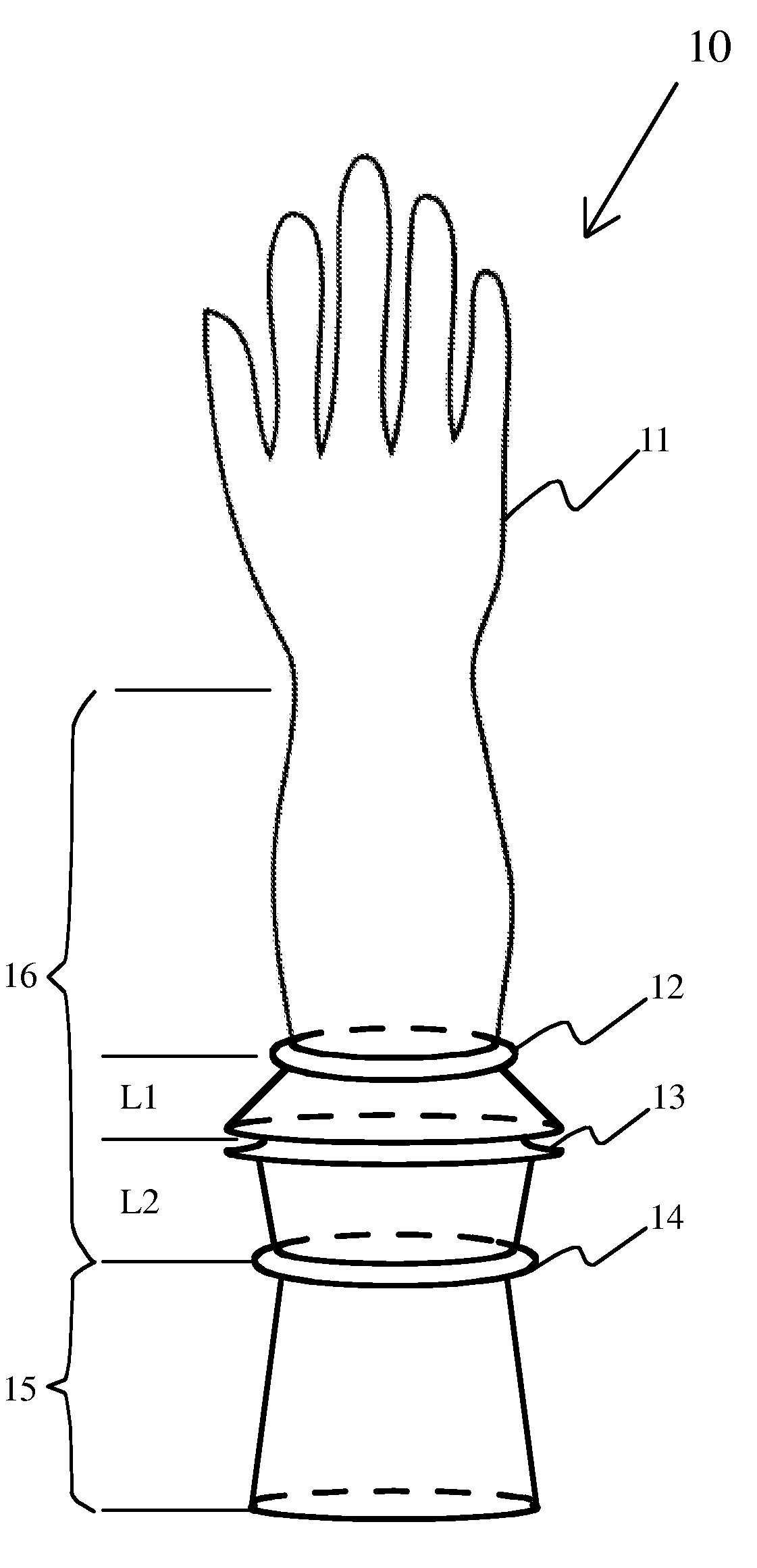
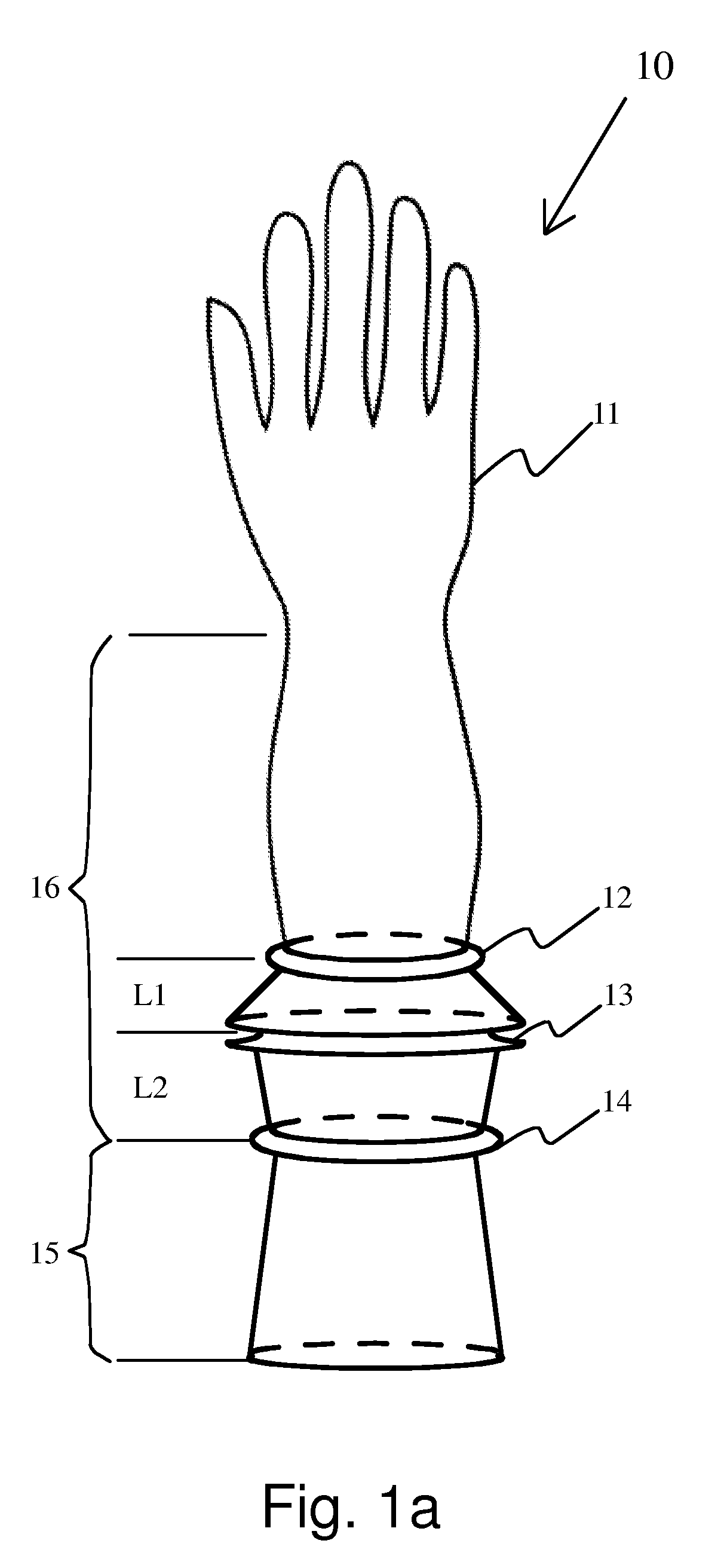
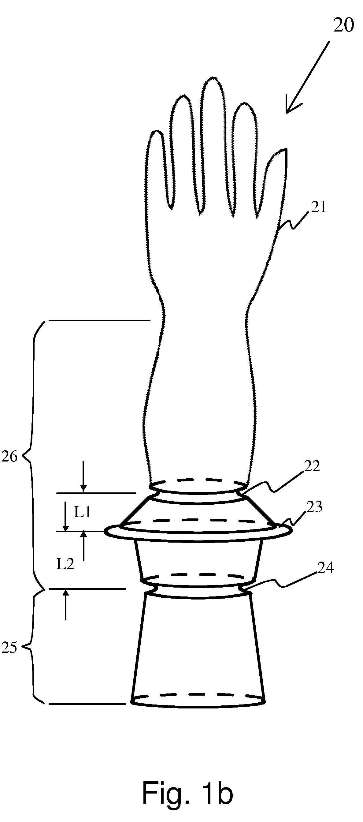
[0016]The glove of the present invention has three geometrically defined ridges in the arm portion of the glove. These ridges are portions where the glove folds easily resulting in the formation of a liquid capturing trough. These ridges may be in the form of easy to bend molded sharp edges or ridges with a C shaped cross section. The glove bends easily along the direction of the open edges of the C shaped ridge while it is relatively more difficult to bend the glove in the opposite direction. In the C shaped ridge arrangement, the first and third ridges of the glove are grooves in the form of a C shaped section that faces away from the arm surface. The second ridge of the glove is a projection that has the C shaped section facing the arm. The first and third ridges have a diameter that is nominally matching to the general taper of the arm portion, but the glove diameter at the second ridge has a larger diameter, typically in the range of 1.2 to 1.5 times the nominal diameter of the arm at this location, based on the general taper of the arm of the glove. The distance between the first and second ridge is L1 and that between second and third ridge is L2. The ratio of L2 to L1 is generally in the range of 1.05 to 1.5 for reasons detailed below.
[0017]When the user initially wears the glove, it covers the hands and the arm of the user. The glove is generally snug and tight at the first and third ridge locations and is looser at the second ridge of the arm portion of the glove. This is due to the larger diameter of the latex glove at the second ridge as compared to the general taper of the arm portion of the glove. The user progressively displaces the third ridge towards the first ridge thereby extending the second ridge outward from the arm to create an integrally formed trough from the glove. The portion of the latex glove between the first ridge and second ridge and the portion of the glove between the second ridge and third ridge extends away from the arm and essentially forms a trough, since the distance L2 is greater than distance L1. The bottom of the trough is in essence at the first ridge while the second ridge forms the lip of the trough. The trough faces the hand portion of the glove and is adapted to catch any liquid that drains down the arm. The trough sidewalls are strong and do not bend back under the weight of the liquid captured due to the presence of two supporting layers of latex. The inner layer of the trough sidewalls is the latex layer between the first and second ridge, while the outer layer is the latex layer between the second and third ridge. The overall diameter of the lip of the trough is determined by the diameter of the second ridge and the angle of the trough is determined by the length between the first and second ridge L1, length between the second and third ridge L2 and the distance L3 between the third ridge and the first ridge which is variable depending upon the displacement by the user. The liquid fill capacity of the glove is determined by the diameter of the second ridge and the angle of the trough thus formed by the user displacing the third ridge toward the first ridge. A smaller displacement of the third ridge toward the first ridge results in a large trough angle, which has a reduced trough volume capability.
[0018]Since the trough is supported by two layers of latex, the interior layer being the latex layer between the first and second ridges and the outer layer being the latex layer between the second and third latex layers, the trough is mechanically strong and can hold the entire filled volume of the liquid without flipping over. Moreover, since the diameter of the glove at the second ridge is substantially larger than the diameter of the arm, any spilled liquid spills away from the arm and does not enter the cuff or the gown of a surgeon. The arm portion below the trough, which is the latex glove that lies below the third ridge, provides protection to the arm of the user in this integrally formed latex glove.
[0019]The glove is gathered by the user by bringing the third ridge towards the first ridge while at the same time extending the second ridge away from the arm crating a trough that is pointed towards the hand portion of the glove. This configuration naturally occurs since the distance L1 between the first and second ridge is smaller than the distance L2 between the second and third ridges. The angle of the cone of the trough progressively decreases and the depth of the trough correspondingly increases thereby increasing the volumetric capacity of the trough to retain liquids. This double layer construction of the trough as formed by the extension of the second ridge results in a rigid structure, which does not readily flop back even when sufficient liquid is accumulated in the nearly full trough.
[0021]This specially formed former is dipped in a coagulant solution such as calcium nitrate and dipped in a latex emulsion to coagulate a latex layer on the former. The thickness of the latex layer formed is generally uniform in cross section. In the case of C shaped ridges, the thickness of the latex layer at the first and third protrusions and second groove is slightly larger than the general thickness of the latex layer, due to the C shaped curvature of the protrusions and groove. The latex layer on the former is washed to remove processing chemicals and heated to a vulcanization temperature in the range of 160-180° C. in an oven to cure the latex layer. The latex layer is now stripped from the former and becomes inverted. In the case of C shaped ridges, the first and third ridges formed by replicating the protrusions of the former now become grooves in the stripped glove and tends to curve the latex away from the interior of the glove. The second ridge, which was a C shaped groove in the former, now becomes a protrusion in the inverted glove, and the glove at the second ridge tends to curve towards the interior of the glove. Thus the larger diameter second ridge naturally likes to extend from the arm assisted by the curvature provided by the first and third C shaped ridges. The behavior is exactly similar when sharp edges are provided at the first second and third ridges. The user can easily move the third ridge towards the first ridge integrally forming an arm trough to capture any liquid that runs down the arm of the glove from the hand portion.
