Optical connector and method for assembling optical connector

a technology of optical connectors and optical cables, applied in the field of optical connectors, can solve the problems of difficult assembly and increase in production costs, and achieve the effects of reducing production costs, reducing parts, and being easy to attach to optical cables

Active Publication Date: 2010-05-25
SUMITOMO ELECTRIC IND LTD
View PDF10 Cites 6 Cited by
  • Summary
  • Abstract
  • Description
  • Claims
  • Application Information

AI Technical Summary

Benefits of technology

[0016]The present invention can provide an optical connector that enables the reduction in the number of parts and can be easily attached to an optical cable. Therefore, the production cost can be reduced and the attachment to the optical cable can be performed smoothly.

Problems solved by technology

The resultant problem is that the production cost rises.
Furthermore, because these parts are small, they are very difficult to assemble.

Method used


Image

  • Optical connector and method for assembling optical connector
  • Optical connector and method for assembling optical connector
  • Optical connector and method for assembling optical connector

Examples


first embodiment

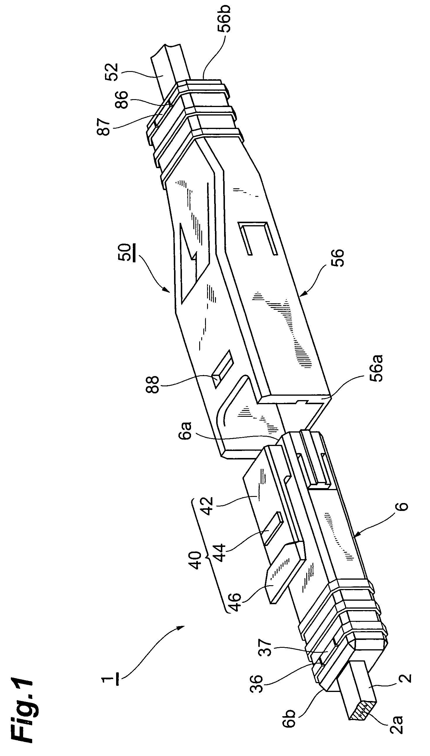
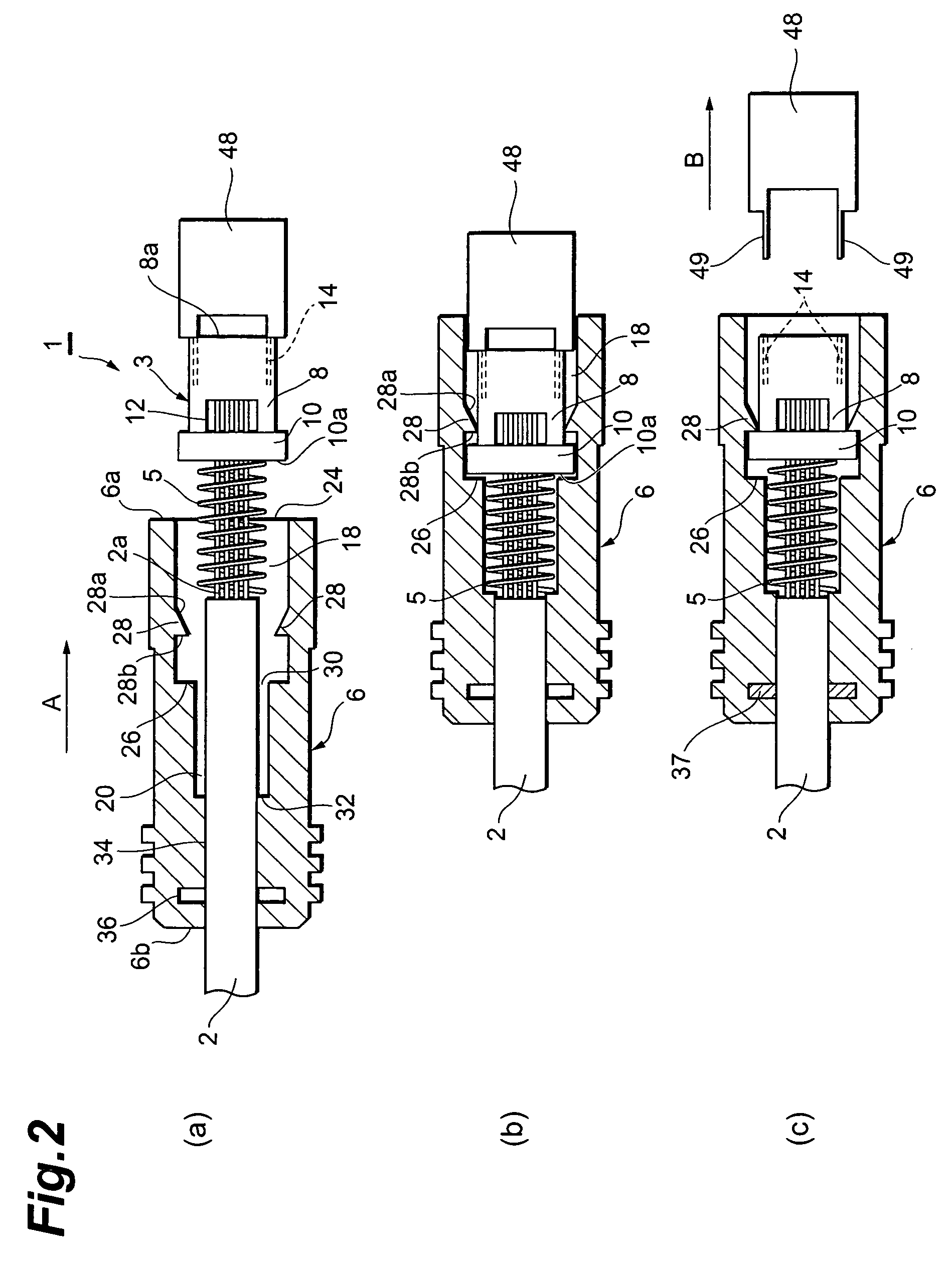
[0024]As shown in FIG. 1, the plug-type optical connector 1 of the first embodiment is an optical connector that will be attached to an optical cable 2 in which an optical fiber 2a is covered with a cable sheath. The plug-type optical connector 1, as shown in FIG. 2, comprises a ferrule 3, a compression coil spring (elastic member) 5, and a plug housing (housing) 6.

[0025]The ferrule 3 serves to hold a distal end portion of the optical fiber 2a. More specifically, it is an MT connector ferrule. The ferrule 3 has a body portion 8 and a collar portion 10 formed integrally with one end side of the body portion 8. Because the collar portion 10 protrudes from the body portion 8, a step is configured between the collar portion 10 and body portion 8.

[0026]Through optical fiber insertion holes (not shown in the figures) for inserting the optical fiber 2a are formed in the body portion 8 and collar portion 10. The optical fiber insertion hole is opened in a distal end surface 8a of the body p...

second embodiment

[0046]A socket-type optical connector of the second embodiment will be described below.

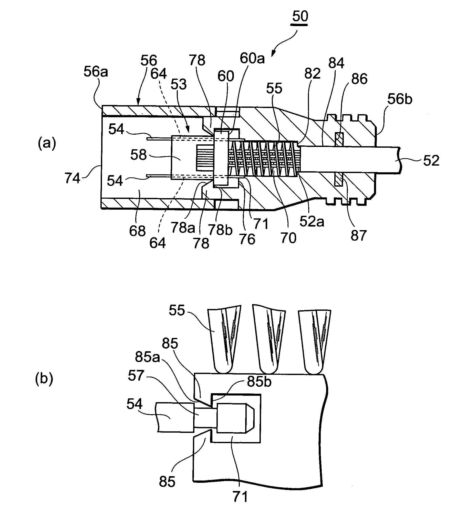
[0047]As shown in FIG. 1, a socket-type optical connector 50 of the present embodiment is an optical connector that will be attached to an optical cable 52 in which an optical fiber 52a is covered with a cable sheath. The socket-type optical connector 50, as shown in FIG. 4, comprises a ferrule 53, a guide pin 54, a compression coil spring (elastic member) 55, and a socket housing (housing) 56.

[0048]The ferrule 53 serves to hold a distal end portion of the optical fiber 52a and is a MT ferrule that is usually used. The ferrule 53 has a configuration substantially identical to that of the ferrule 3 in the plug-type optical connector 1 of the first embodiment. A body portion 58 of the ferrule 53 is equivalent to the body portion 8 of the ferrule 3, and a collar portion 60 of the ferrule 53 is equivalent to the collar portion 10 of the ferrule 3.

[0049]A pair of guide pin insertion holes 64 are formed...


PUM


Abstract

To provide an optical connector that enables the reduction in the number of parts and can be easily attached to an optical cable, a concave portion 18 for a ferrule is formed in a plug housing 6, and a ferrule 3 is inserted from the side of a collar portion 10 into the concave portion 18 for a ferrule. A hook portion 28 for a ferrule is provided in a protruding condition inside the plug housing 6. The collar portion 10 is guided by the hook portion 28 for a ferrule, which has been elastically deformed, and moves toward a bottom surface 26 of the concave portion 18 for a ferrule. Where the collar portion 10 reaches a space between the bottom surface 26 and the hook portion 28 for a ferrule, the hook portion 28 for a ferrule is elastically restored. Therefore, even if the collar portion 10 tries to move toward an opening 24 of the concave portion 18 for a ferrule, the collar portion is locked by the hook portion 28 for a ferrule and the movement is inhibited. Thus, in the plug-type optical connector 1, the ferrule 3 can be positioned by inserting into the plug housing 6 and moving.

Description

BACKGROUND OF THE INVENTION[0001]1. Field of the Invention[0002]The present invention relates to an optical connector that can be used when abutting and connecting optical fibers exposed from optical cables, and to a method for assembling the optical connector.[0003]2. Related Background Art[0004]A conventional optical connector is known that comprises, for example as described in Patent Document 1, a ferrule having a body portion (cylindrical body) and a collar portion (collar member), a stop ring that holds a rear end portion of the collar portion, a plug frame that holds a distal end portion of the collar portion, and a housing (plug housing) that covers the plug frame. In the conventional optical connector, the ferrule is positioned inside the optical connector by sandwiching the collar portion between the stop ring and the plug frame.[Patent Document 1] Japanese Patent Application Laid-open No. 11-305075.SUMMARY OF THE INVENTION[0005]However, in the conventional optical connect...

Claims


Application Information

Patent Timeline
Patent Type & Authority Patents(United States)
IPC IPC(8): G02B6/38
CPCG02B6/3821G02B6/3885G02B6/3869G02B6/3893G02B6/3882
Inventor FUKUI, JUNJISAKURAI, WATARUTAMURA, MITSUAKI
Owner SUMITOMO ELECTRIC IND LTD
Why Eureka
Try Eureka