Turbo-engine stator blading, turbo-engine comprising the blading and turbo-engine blade

a technology of stator blades and turbo engines, which is applied in the direction of propellers, propulsive elements, water-acting propulsive elements, etc., can solve the problems of difficult mounting and difficult mounting of blades, and achieve the effects of low manufacturing cost, high machining accuracy and greater simplicity in manufacturing terms

Active Publication Date: 2010-05-25
TECHSPACE AERO
View PDF16 Cites 14 Cited by
  • Summary
  • Abstract
  • Description
  • Claims
  • Application Information

AI Technical Summary

Benefits of technology

[0008]By virtue of the invention, each blade is placed in the blading by its platform being inserted into a receptacle of complementary form. Mounting is thus very simple to carry out, without the risk of error. Since the receptacles are obtained by machining, any human error is avoided, since the mounting accuracy of the blading is ensured by the precision of the machines used for forming the receptacles and platforms, independently of the mounting operation itself. Moreover, as well as, of course, the platforms, it is the ring which delimits the corresponding portion of the flow section: the leak-tightness of the assembly is thus ensured, its rigidity, moreover, being increased.
[0015]Advantageously, the blades are in one piece with their platform. This results in much greater simplicity in manufacturing terms and a higher rigidity of the blades.

Problems solved by technology

Such bladings have the disadvantage of being difficult to mount, since the blade platforms delimiting the flow section must be perfectly contiguous.
Moreover, in the event that the orientation of the blades differs according to their angular position, this mounting is all the more difficult because it is then necessary to provide blades which are of different forms and / or the platforms of which are different, which have to be mounted in succession in the correct order.

Method used


Image

  • Turbo-engine stator blading, turbo-engine comprising the blading and turbo-engine blade
  • Turbo-engine stator blading, turbo-engine comprising the blading and turbo-engine blade

Examples


Embodiment Construction

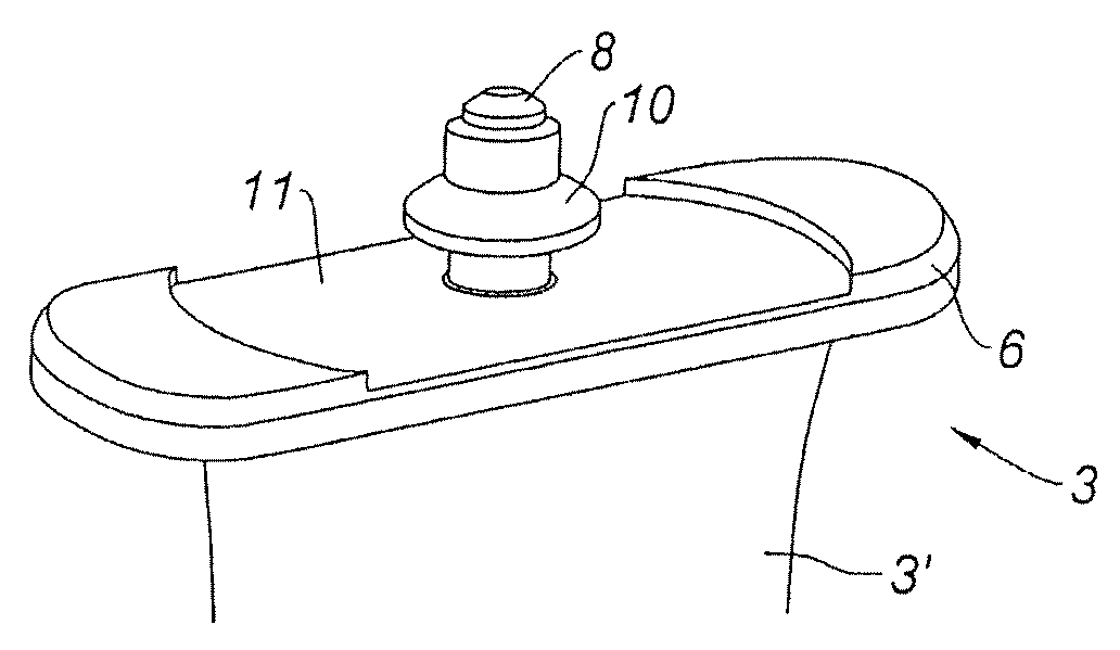
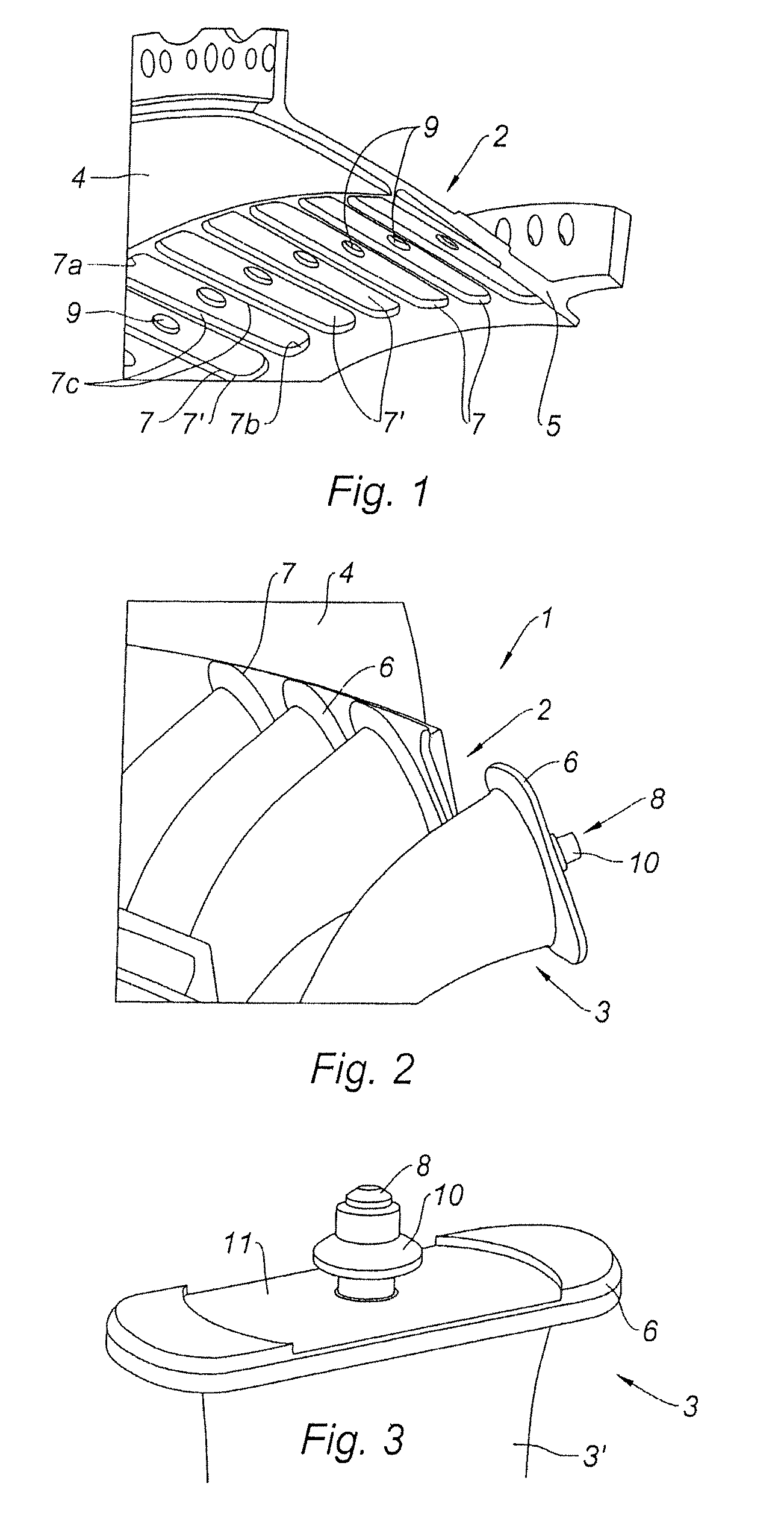
[0024]Referring to FIGS. 1 and 2, the axial stator blading 1 of the invention comprises a ring 2, in this particular case an outer ring, and blades 3 mounted fixedly on the ring 2. By axial blading is meant a blading which extends within an axially flowing gas stream and the blades of which extend substantially perpendicularly with respect to the direction of flow of the stream. Where fixed blades are concerned, these are generally referred to as bolted blades. In this particular case, the stator blading 1 is a straightener blading located in the lower-pressure compressor of a turbojet. FIGS. 1 and 2 show the zone 4 of abraidable material which is located upstream of the straightener blades 3 with which the moving blades of the preceding rotor stage of the compressor are intended to fit closely. It will be recalled that the invention applies more generally to any stator blading comprising fixed blades mounted on a generally outer ring.

[0025]For the ring 2 comprises a wall 5 of revol...


PUM


Abstract

A turbo-engine stator blading is disclosed. The turbo-engine stator blading includes a crown of fixed blades mounted on a ring. Each blade includes a platform and each blade is fastened to the ring. The ring includes a plurality of individual receptacles for the each of the platforms, the receptacles being machined in the thickness of the ring, the form of each receptacle being complementary to that of the corresponding platform. By means of the receptacles, the mounting of the blades within the blading is both simple and accurate.

Description

BACKGROUND OF THE INVENTION[0001]The invention relates to the field of turbo-engines comprising stator blading.[0002]A turbo-engine, whether it be a compressor, a turbine or any other engine, such as a turbojet, comprising at least one stator blading. By stator blading is meant a set of fixed blades mounted in the form of a crown on an outer ring and / or an inner ring. As an example, mention may be made of flow-straightening bladings in compressors or turbines, generally arranged between two moving-blade stages, or else flow-straightening bladings placed just downstream of the blower in double-flow turbojets.[0003]The blades of some axial stator bladings are oriented differently, depending on their angular position, in order to adapt the flow which they guide to the aerodynamic constraints of the engine.[0004]Various forms of fastening of the blades on the outer ring of the blading are known. In document EP 0,953,729, each blade, inserted in a bore of the inner ring, comprising an ou...

Claims


Application Information

Patent Timeline
Patent Type & Authority Patents(United States)
IPC IPC(8): F04D29/44
CPCF01D9/042
Inventor LHOEST, ANDREBROERS, GEORGESCOLMANT, THOMASDUCHAINE, GEORGESWERY, XAVIER
Owner TECHSPACE AERO
Why Eureka
Try Eureka