Closing link for a bicycle chain

a technology of closing link and chain, which is applied in the direction of chain elements, chains, chains, etc., can solve the problems of derailleurs, pin heads protruding beyond the outer surface of the outer link plate, and adverse effects on the shifting behavior of the chain, so as to reduce the lateral movement of the chain

Active Publication Date: 2010-05-25
SRAM
View PDF22 Cites 11 Cited by
  • Summary
  • Abstract
  • Description
  • Claims
  • Application Information

AI Technical Summary

Benefits of technology

[0005]The present invention provides a chain closing link with a flush pin head geometry and reduces the lateral movement of the chain in the region of the closing link. Further, the closing link provides a secure chain pin connection between mating outer link plates and safeguards against disassembly of the chain.
[0007]In one embodiment of the present invention, a span between the unrecessed portions of the sides of the displacement region decreases from the larger diameter end toward the smaller diameter end to safeguard against disassembly of the closing link. The narrowest span is smaller than the diameter of the pin groove to provide a latching function. This configuration protects an inadvertent release of the pin head from the countersink and movement of the pin toward the displacement region caused by a lateral impact against the chain.
[0008]In another embodiment of the present invention, a span between the recessed portions of the sides of the displacement region decreases from the larger diameter end toward the countersink. The narrowest span is smaller than the diameter of the pin head. This configuration safeguards against disassembly by latching the chain pin into its end position with the pin head seated in the countersink. The recessed portions may have a flat base proximate the countersink and a sloped base proximate the larger diameter end, the sloped base sloping or tapering down from the flat base toward the larger diameter end to ease installation. Preferably, the height of the pin head does not exceed the depth of the countersink.
[0010]In the present invention, the pin head and the countersink are configured to provide a flush connection. Previously, during the closing of the closing link, the pin head protruded beyond the outer link plate before it could enter the countersink in the end position. In contrast, in the present invention, the surface of the pin groove slides along the outside of the outer link plate and the pin head displaces along the recessed portion from the larger diameter end to the countersink, allowing the length of the chain pin to be reduced. This configuration provides a closing link that permits a narrower chain that can be used with derailleurs having more sprockets. Further, reducing the distance between the pin foot and pin head also reduces play, in the longitudinal direction of the chain pin, between the pin head and the opposite outer link plate, thereby reducing the lateral movement of the chain in the region of the closing link.
[0011]Another objective of the present invention is to provide a closing link that safeguards against inadvertent disconnection of the closing link. Further, the two outer link plates of the closing link may be connected and disconnected without a tool.

Problems solved by technology

One drawback of the above closing link is that the pin head protrudes beyond the outer surface of the outer link plate which is not suitable for derailleurs with many sprockets having minimal spacing therebetween.
Another drawback is that a large groove on the pin head results in undesirable lateral movement of the chain in the region of the closing link that may have an adverse effect on the shifting behavior of the chain.

Method used


Image

  • Closing link for a bicycle chain
  • Closing link for a bicycle chain
  • Closing link for a bicycle chain

Examples


Embodiment Construction

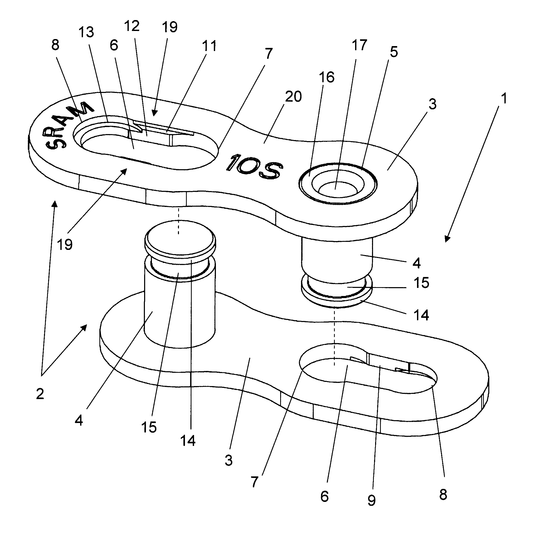
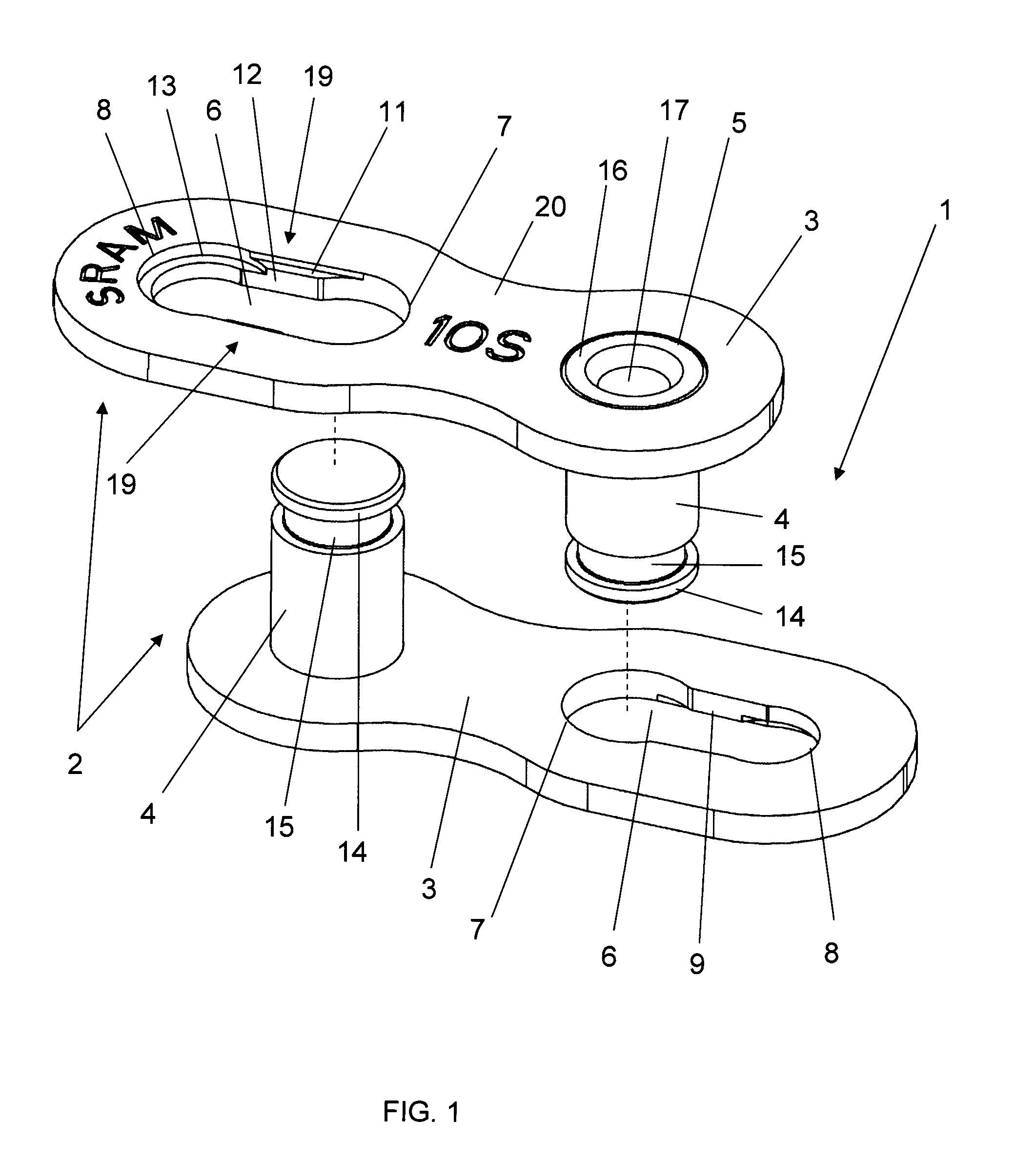
[0019]FIG. 1 illustrates a closing link 1 according to one embodiment of the present invention. The closing link 1 generally includes two closing parts 2, each including an outer link plate 3 and a chain pin 4 extending therefrom. The outer link plate 3 includes an elongated hole 6. To connect the closing link 1, the chain pins 4 of the closing parts 2 are inserted into the elongated holes 6 of the mating closing part 2.

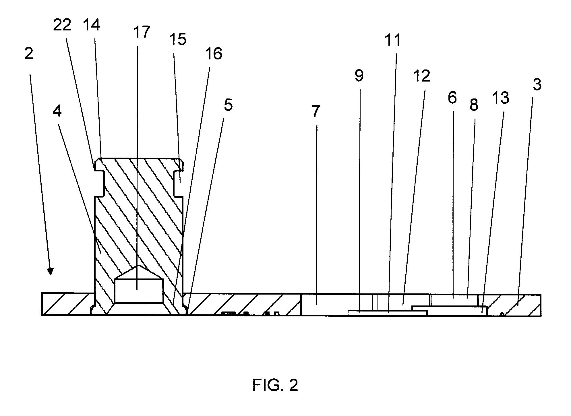
[0020]The chain pin 4 has a head 14 at one end, a foot 16 at the other end and a groove 15 therebetween. The outer link plate 3 also includes a pin bore 5 for permanent attachment of the pin foot 16. The elongated hole 6 has a larger diameter end 7, a smaller diameter end 8 and a displacement region 9 therebetween. The larger diameter end 7 has a larger diameter than the pin head 14 for receiving the pin head 14 of the mating chain pin. The smaller diameter end 8 has a countersink 13 for seating the pin head 14. The displacement region 9 is the path along which the c...


PUM


Abstract

A closing link for a bicycle chain that includes a first outer link plate having a first elongated hole and a first chain pin extending therefrom and a second outer link plate having a second elongated hole and a second chain pin extending therefrom. The first chain pin is received in the second elongated hole and the second chain pin is received in the first elongated hole Each chain pin has a head at one end, a foot at the other end and a groove therebetween. Each elongated hole has a larger diameter end, a smaller diameter end and a displacement region therebetween. The larger diameter end has a diameter larger than a diameter of the pin head. The smaller diameter end receives the groove of the chain pin and includes a countersink to receive the pin head. The displacement region includes sides having recessed and unrecessed portions. The recessed portions have a smaller depth than a depth of the countersink at least in the region of the countersink.

Description

BACKGROUND OF THE INVENTION[0001]The present invention relates to bicycle chains and more particularly to a closing link for a bicycle chain that may be used to connect and disconnect adjoining chain links without a tool.[0002]Driving chains for bicycles include chain links pivotably arranged with respect to each other to form a closed loop to transmit the chain driving force. Interior spaces between the chain links receive the teeth of the sprockets or chainrings. To easily remove the chain from bicycle for maintenance, a closing link is provided to disconnect the chain.[0003]DE 44 31 614 A1 discloses a closing link for a chain. The closing link has a narrow design and includes a pair of parallel link plates and a pair of parallel pins connected therebetween. Each plate includes an elongated hole that has a large diameter at one end to allow insertion of the pin. Each pin includes a groove near the pin head that is wider than the thickness of the link plate and the position of the ...

Claims


Application Information

Patent Timeline
Patent Type & Authority Patents(United States)
IPC IPC(8): F16G13/02F16G13/00F16G15/06
CPCF16G15/00F16G13/06
Inventor SANTOS, PEDRO
Owner SRAM
Why Eureka
Try Eureka