Method of fabricating a longitudinal frame member of a trench-forming assembly

a technology of longitudinal frame member and assembly, which is applied in the direction of foundation engineering, artificial islands, non-electric welding apparatus, etc., can solve the problems of increasing the cost and labor required for assembly and disassembly of wooden forms, and reducing the efficiency of the flow of liquid through the trench. , to achieve the effect of reducing the lateral movement of frame members

Active Publication Date: 2005-10-27
ABT
View PDF42 Cites 9 Cited by
  • Summary
  • Abstract
  • Description
  • Claims
  • Application Information

AI Technical Summary

Benefits of technology

[0012] The present invention provides an improved trench-forming assembly and method of forming a trench, where the trench-forming assembly includes one or more mounting bracket assemblies. In this regard, the mounting bracket assemblies are capable of extending across a form body of the trench-forming assembly such that the mounting bracket assembly can be removably engaged with the frame members of the trench-forming assembly when the frame members are engaged with the form body. As such, the trench-forming assembly can bring the frame members into snug contact with opposite sides of the form body to thereby reduce lateral movement of the frame members with respect to the form body. In addition, the mounting bracket assembly can extend beyond the form body. Advantageously, then, the form body and frame members can be suspended from the mounting bracket assembly, when the form body and frame members are placed in a ditch, such as during formation of a trench.
[0019] In one advantageous embodiment, the horizontal leg and the securing leg are integral with the vertical leg, and the end member is integral with the horizontal leg. Thus, according to another aspect of the present invention, a method is provided for fabricating a longitudinal frame member of a trench-forming assembly. The method begins by providing a molten material. Then, the molten material is extruded through a die shaped to define the frame member which advantageously has the same profile along its entire length, namely, a vertical leg, a horizontal leg and a securing leg integral with opposing edges of the vertical leg, and an end member integral with an edge of the horizontal leg. More particularly, the molten material can be extruded through a die shaped to define the horizontal leg to include an engagement portion and a support portion that extend outwardly from a top edge of the vertical leg in opposing directions. The molten material can also be extruded through a die shaped to define the securing leg to includes an engagement portion, and includes a connecting portion that extends at least one of downwardly and outwardly from a bottom edge of the vertical leg in opposing directions. Further, the molten material can be extruded through a die shaped to define the end member to include an edge portion and a base portion that extends outwardly from an edge of the support portion. In addition, the die can be shaped such that extruding the molten material through the die defines the horizontal leg and securing leg to each include an engagement portion that extend outwardly from a respective edge of the vertical leg such that the engagement portions are adapted to engage a form body of the trench-forming assembly. Moreover, by extruding the frame member, the frame member can be formed in an economic manner.
[0020] According to yet another aspect of the present invention, a method is provided for forming a trench of a predetermined shape. According to the method, a trench-forming assembly is provided, where the trench-forming assembly again comprises a removable longitudinal form body including a top surface, a bottom surface and opposed side surfaces, and defining the predetermined shape. The trench-forming assembly also includes a pair of longitudinal frame members in engagement with respective side surfaces of the form body, where each frame member includes a support surface. The method continues by extending at least one mounting bracket assembly laterally across the top surface of the form body and thereafter removably engaging each mounting bracket assembly with a downwardly facing side of the support surfaces of the frame members. Advantageously, the mounting bracket assembly extends beyond the form body and frame members. In embodiments where the mounting bracket assembly includes a pair of downturned bias members, each mounting bracket assembly can be engaged such that the downturned bias members effectively contact upwardly facing surfaces of respective frame members.

Problems solved by technology

Correspondingly, the inside surface of the trench formed by the wooden form is relatively uneven which reduces the efficiency of the flow of liquid through the trench.
In addition, the assembly and disassembly of the wooden forms is both costly and labor intensive.
The relatively large cost and labor required for assembly and disassembly of the wooden forms is increased in the formation of long trenches, and even further increased in the formation of trenches having a pitched or slanted bottom surface to facilitate drainage.
If the frame members and, in turn, the grate are not properly aligned, the grate, the frame members and / or the cementitious trench itself may be damaged by the resulting movement of the grate.
Such relative movement is typically undesirable since it may adversely alter the relative alignment of the frame members such that the grate no longer sits evenly upon the rails.

Method used


Image

  • Method of fabricating a longitudinal frame member of a trench-forming assembly
  • Method of fabricating a longitudinal frame member of a trench-forming assembly
  • Method of fabricating a longitudinal frame member of a trench-forming assembly

Examples


Embodiment Construction

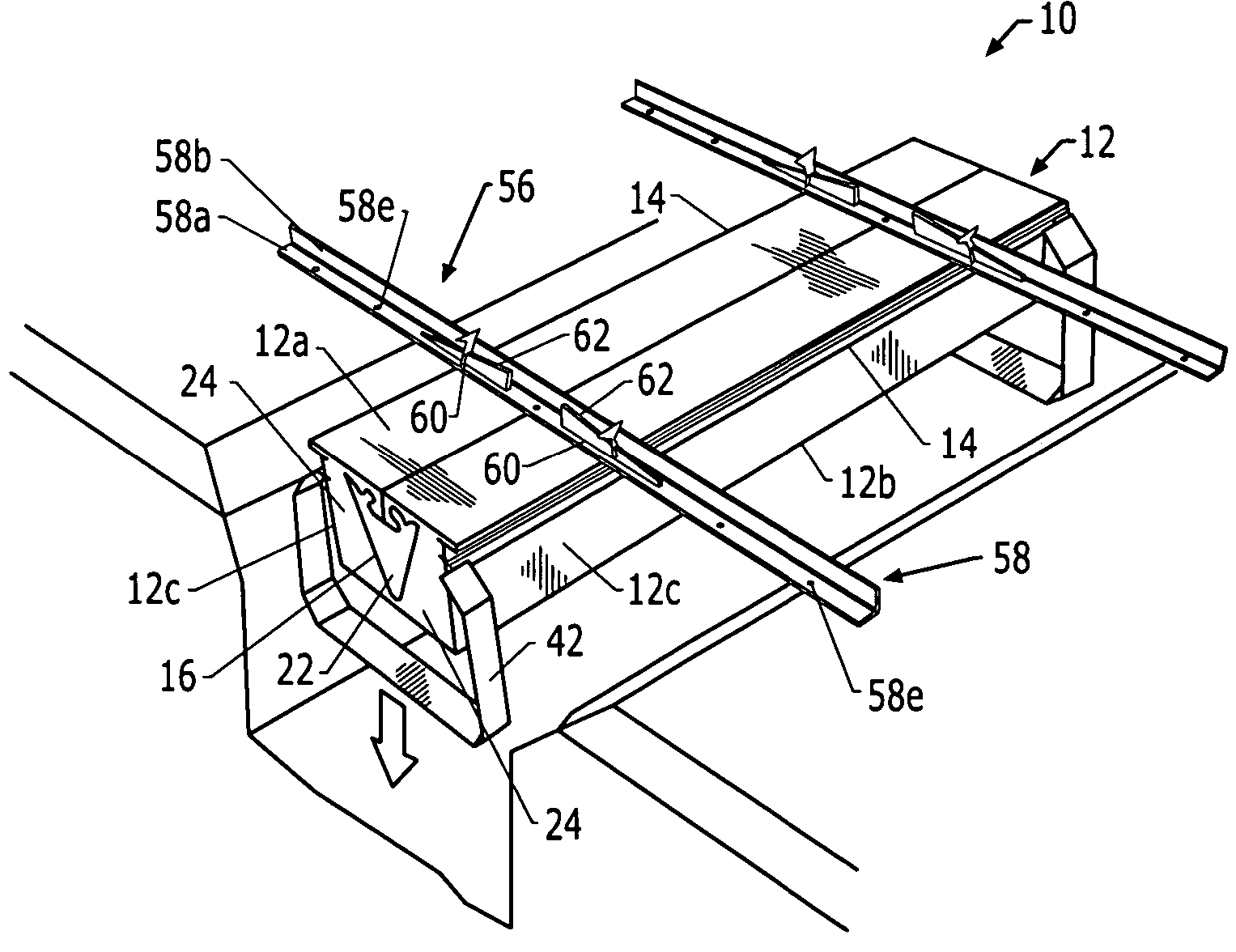
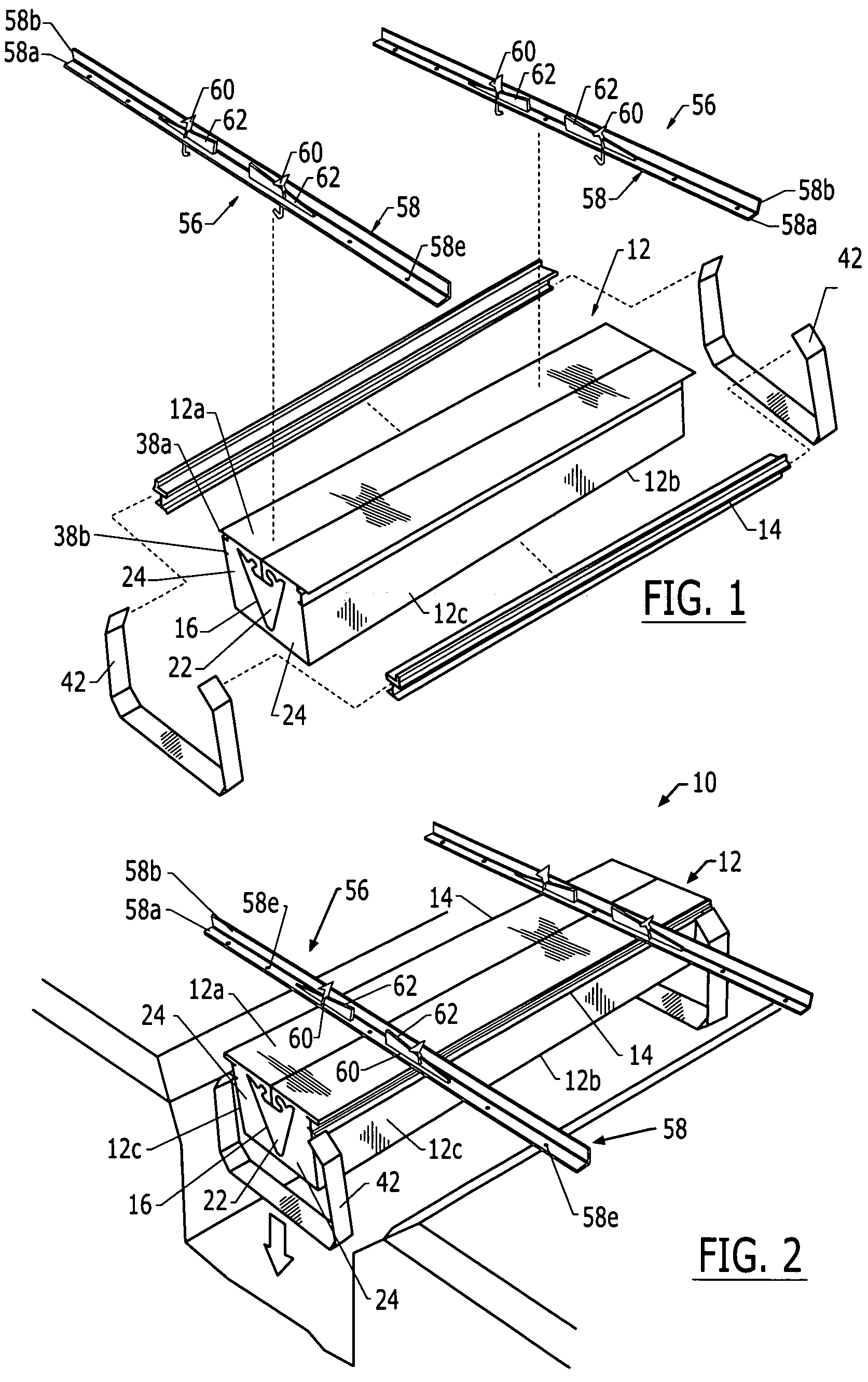
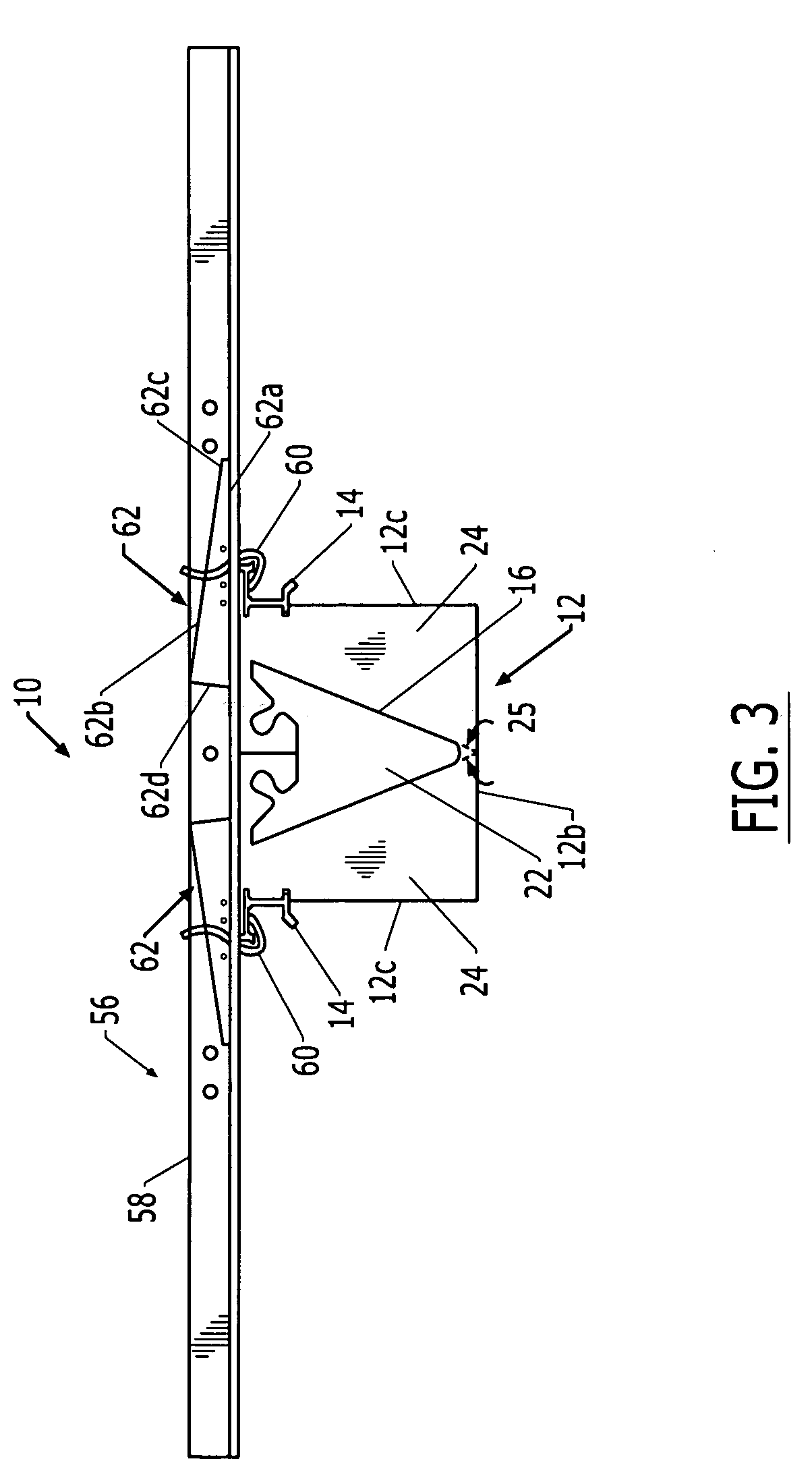
[0043] The present invention now will be described more fully hereinafter with reference to the accompanying drawings, in which preferred embodiments of the invention are shown. This invention may, however, be embodied in many different forms and should not be construed as limited to the embodiments set forth herein; rather, these embodiments are provided so that this disclosure will be thorough and complete, and will fully convey the scope of the invention to those skilled in the art. Like numbers refer to like elements throughout.

[0044]FIGS. 1-3 illustrate a trench-forming assembly 10 for forming a trench of a predetermined shape. The trench-forming assembly can be utilized to form a trench for any of a number of different applications. For example, the trench-forming assembly can be used to form trenches for drainage systems in building floors facilities to collect, remove, and / or recycle excess water or other liquids. These trenches can also be used as utility chases to provide...


PUM

PropertyMeasurementUnit
interior angleaaaaaaaaaa
sizesaaaaaaaaaa

Abstract

An assembly is provided for forming a trench of a predetermined shape. The trench-forming assembly includes a removable longitudinal form body, a pair of frame members and at least one mounting bracket assembly. The form body is capable of shaping a moldable trench forming composition poured around the form. Each frame member includes a support surface, and is in engagement with a respective side surface of the form body. The mounting bracket assemblies, each of which can include a mounting bracket and a pair of hook members, extend laterally across the top surface of the form body. In this regard, each mounting bracket assembly removably engages a downwardly facing side of the support surface of the frame members.

Description

CROSS REFERENCE TO RELATED APPLICATIONS [0001] This application is a Divisional of U.S. application Ser. No. 10 / 282,517, filed Oct. 29, 2002, which is hereby incorporated herein in its entirety by reference.FIELD OF THE INVENTION [0002] The present invention relates generally to systems and methods for forming a trench and, more particularly, relates to a mounting bracket assembly for connecting frame members of a trench-forming assembly and an associated method of fabricating frame members. BACKGROUND OF THE INVENTION [0003] Drainage and other trenches of various sizes and shapes are desirable for a number of applications. For example, manufacturing facilities typically require drainage systems that include trenches formed in the building floors to collect, remove, and / or recycle excess water or other liquids. These trenches may also be used as utility chases to provide temporary or permanent routing of electrical lines, pipes, conduits or the like below the level of the building f...

Claims


Application Information

Patent Timeline
Patent Type & Authority Applications(United States)
IPC IPC(8): E01C19/50
CPCE01C19/506Y10T428/12375Y10T428/12299Y10T428/1241
Inventor WALLACE, TIMOTHY HAROLDWILLIAMS, BARRY CLIFTON
Owner ABT
Why Eureka
Try Eureka