Drill bits and tools for subterranean drilling

Inactive Publication Date: 2009-04-02
BAKER HUGHES INC
View PDF27 Cites 10 Cited by
  • Summary
  • Abstract
  • Description
  • Claims
  • Application Information

AI Technical Summary

Benefits of technology

[0008]In one embodiment, a drill bit includes at least one extension pad for increasing stability and reducing lateral motion acting on the drill bit while drilling a subterranean formation. The drill bit includes a bit body having a face extending to a gage region, at least one blade extending longitudinally and radially outward over the face of the bit body from a longitudinal axis thereof, the at l

Problems solved by technology

However, increased rotational speed also tends to decrease the life of a drill bit due to premature damage to and destruction of cutting elements, commonly polycrystalline diamond compacts (PDC's).
In the latter instance, aggressive cutter placement and orientation creates a high tangential cutting force relative to the normal force applied to the bit and aggravates the imbalance.
In any event, these imbalance forces tend to cause the drill bit to rotate or roll about the bore hole in a direction counter to the normal direction of rotation imparted to the bit during drilling.
Furthermore, while the prior art provides for focusing or directing the imbalance forces as a resultant side force vector toward a particular side of the bit, it does so by compromising aggressiveness of the bit, particularly affecting the placement and aggressiveness of cutting elements.
Moreover, while the above-referenced patents reduce hole wall tangential forces which are generally noted to induce whirl, they do not protect the cutting elements from chipping as a result of the impact loads caused by vibrational instabilities commensurate with bit whirl, particularly when drilling in harder subterranean formatio

Method used


Image

  • Drill bits and tools for subterranean drilling
  • Drill bits and tools for subterranean drilling
  • Drill bits and tools for subterranean drilling

Examples


Example

[0017]In the description which follows, like elements and features among the various drawing figures are identified for convenience with the same or similar reference numerals.

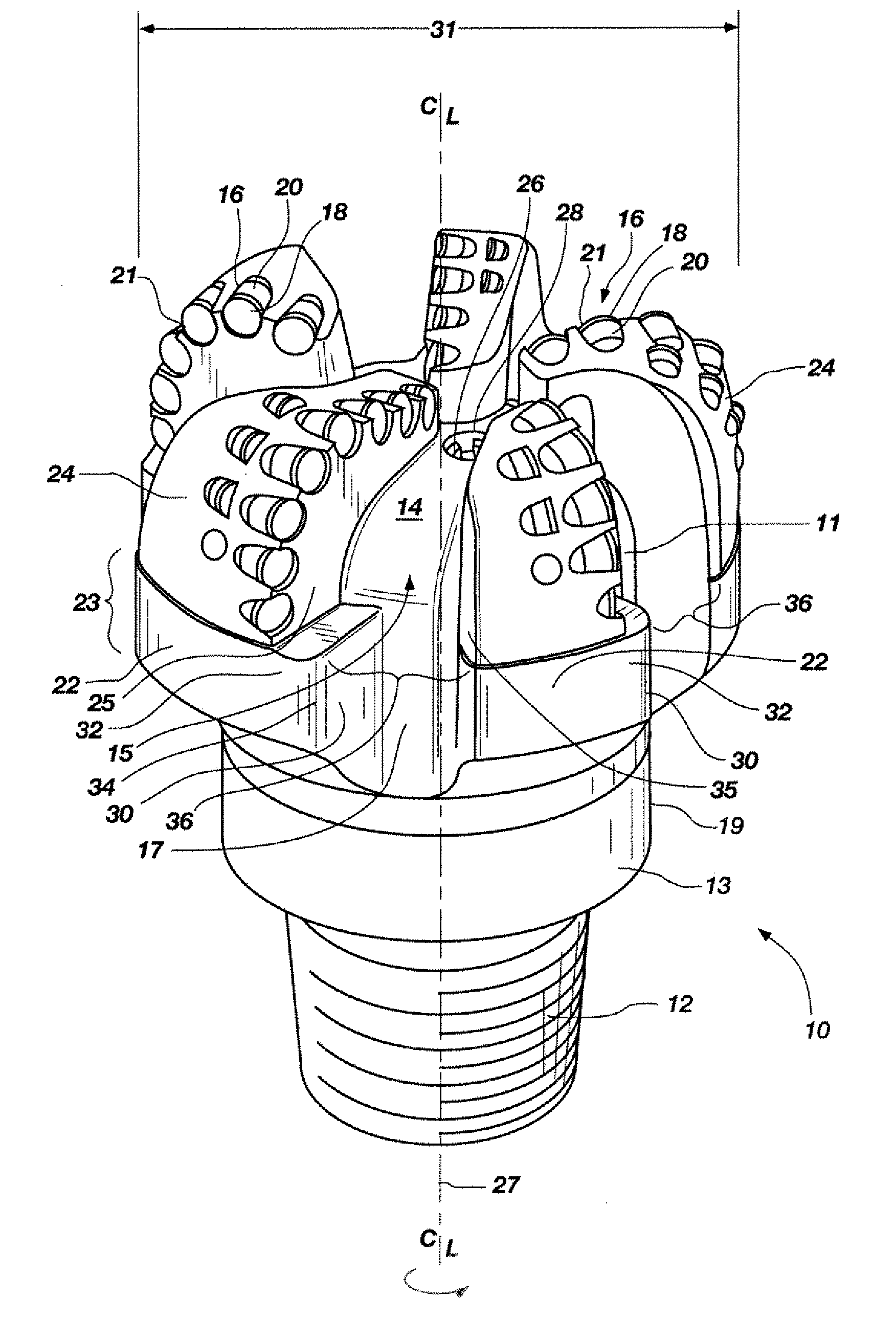
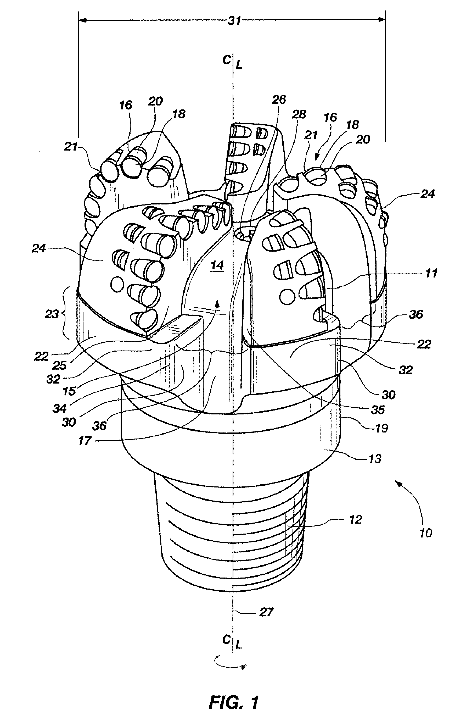
[0018]FIG. 1 shows a perspective, inverted (with respect to the usual orientation thereof during drilling) view of a drill bit 10 configured with extension pads 30, according to an embodiment of the invention. The drill bit 10 is configured as a fixed cutter rotary full bore drill bit, also known in the art as a “drag” bit. The drill bit 10 includes a bit crown or body 11 comprising, for example, tungsten carbide infiltrated with a metal alloy binder, a machined steel casting or forging, or a sintered tungsten or other suitable carbide, nitride or boride as discussed in further detail below, and coupled to a support 19. The support 19 includes a shank 13 and a crossover component (not shown) coupled to the shank 13 in this embodiment of the invention. It is recognized that the support 19 may be made from a uni...


PUM


Abstract

A drill bit includes at least one extension pad extending rotationally forward or backward of an associated blade in a gage region of the bit body. The extension pad includes a circumferential bearing surface that extends the circumferential bearing surface of the associated blade and reduces the chordal drop between any blade having an extension pad associated therewith and a circumferentially adjacent blade toward which the extension pad protrudes. A drill bit that reduces a chordal drop segment extending across a junk slot is also disclosed.

Description

FIELD OF INVENTION[0001]The invention, in various embodiments, relates to drill bits and tools for subterranean drilling and, more particularly, to a drill bit or tool incorporating structure for enhancing stabilization and reducing lateral motion.BACKGROUND[0002]Fixed cutter rotary drill bits for subterranean earth boring have been employed for decades. It is well known that increasing the rotational speed of such drill bit, for a given weight on bit and subject to the ability of the bit's hydraulic structure to adequately clear formation cuttings from the bit, increases the rate of penetration of the drill string. However, increased rotational speed also tends to decrease the life of a drill bit due to premature damage to and destruction of cutting elements, commonly polycrystalline diamond compacts (PDC's).[0003]It has been recognized that cutting element destruction, particularly at higher rotational speeds, is at least in part attributable to a phenomenon known as “whirl” or “b...

Claims


Application Information

Patent Timeline
IPC IPC(8): E21B10/60
CPCE21B10/42
Inventor ERNST, STEPHEN J.BILEN, JUAN MIGUEL
Owner BAKER HUGHES INC
Why Eureka
Try Eureka