Shielded module having compression overmold

Active Publication Date: 2017-01-26
SKYWORKS SOLUTIONS INC
View PDF1 Cites 10 Cited by
  • Summary
  • Abstract
  • Description
  • Claims
  • Application Information

AI Technical Summary

Benefits of technology

[0019]For purposes of summarizing the disclosure, certain aspects, advantages and novel features of the inventions have been described herein. It is to be understood that not necessarily all such advantages may be achieved in accordance with any particular

Problems solved by technology

This technique is prone to trapped air pockets resulting from imbalanced flow, uneven re

Method used


Image

  • Shielded module having compression overmold
  • Shielded module having compression overmold
  • Shielded module having compression overmold

Examples


Example

[0031]The headings provided herein, if any, are for convenience only and do not necessarily affect the scope or meaning of the claimed invention.

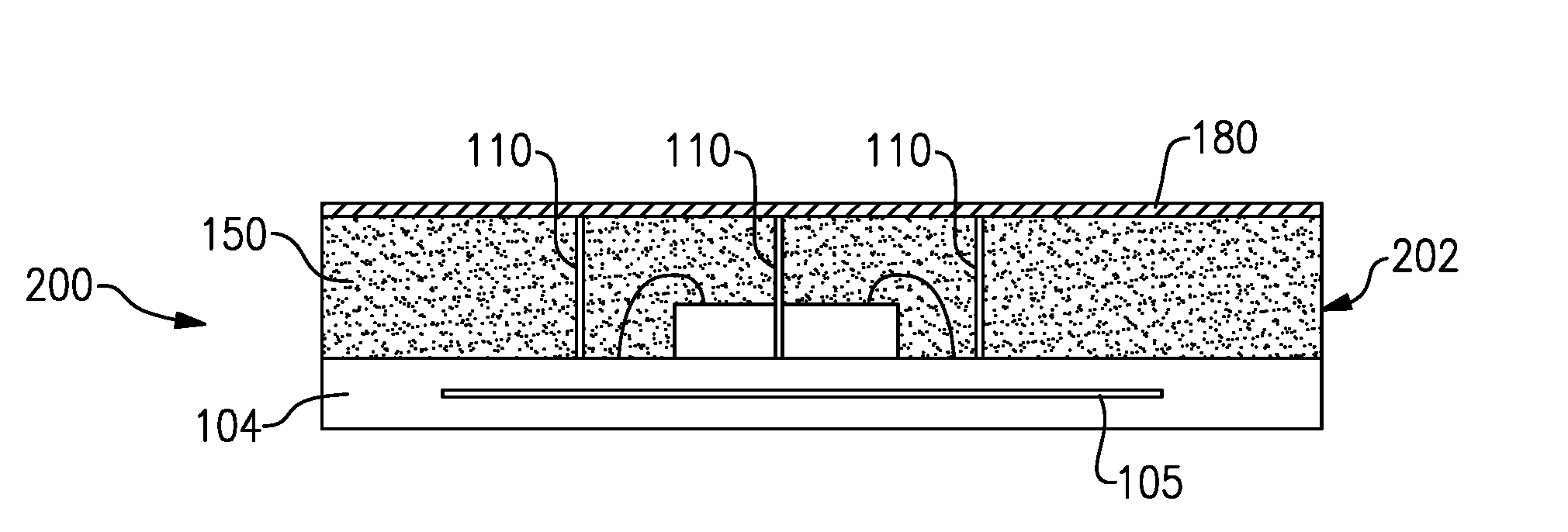
[0032]Described herein are examples of devices and methods related to a shielded module having a compression-molded structure such as an overmold. Such a module can include radio-frequency (RF) shielding facilitated by, for example, shielding-wirebonds. Additional details concerning such shielding-wirebonds can be found, for example, in Appendix A of U.S. Provisional Application No. 62 / 168,872 filed May 31, 2015, entitled SHIELDED MODULE HAVING COMPRESSION OVERMOLD, which is expressly incorporated by reference in its entirely, and which is to be considered part of the specification of the present application.

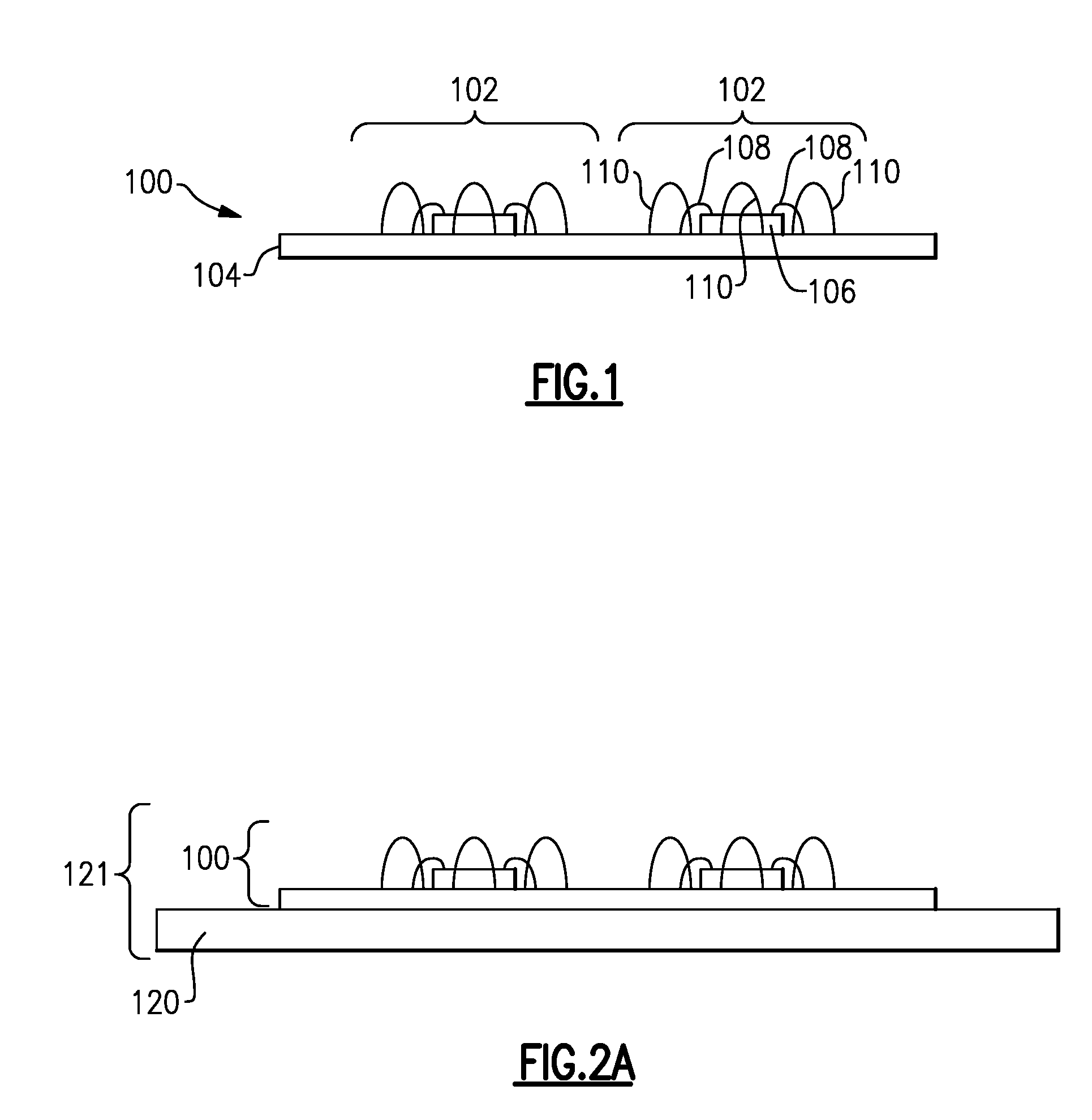
[0033]FIG. 1 shows a side view of a partially completed panel 100 having a packaging substrate 104. Such a packaging substrate 104 can include, for example, a laminate substrate. Formed or mounted on such a packaging substrate 104 are t...


PUM


Abstract

A method for fabricating a radio-frequency (RF) module is disclosed, the method including forming or providing a first assembly that includes a packaging substrate and an RF component mounted thereon, the first assembly further including one or more shielding-wirebonds formed relative to the RF component, and forming an overmold over the packaging substrate to substantially encapsulate the RF component and the one or more shielding-wirebonds, the overmold formed by compression molding that includes reducing a volume of melted resin in a direction having a component perpendicular to a plane defined by the packaging substrate.

Description

CROSS-REFERENCE TO RELATED APPLICATION(S)[0001]This application claims priority to U.S. Provisional Application No. 62 / 168,872 filed May 31, 2015, entitled SHIELDED MODULE HAVING COMPRESSION OVERMOLD, the disclosure of which is hereby expressly incorporated by reference herein in its entirety.BACKGROUND[0002]Field[0003]The present disclosure relates to module shielding technology for various semiconductor devices.[0004]Description of the Related Art[0005]Existing techniques for forming mold caps on packaged semiconductor parts have several limitations and disadvantages. One such existing technique is transfer mold technology, which involves pushing fluid resin into one end of a cavity containing the parts to be capped with mold compound. This technique is prone to trapped air pockets resulting from imbalanced flow, uneven resin distribution, and occasionally damage or warpage to wires on the semiconductor parts. Accordingly a safer and more efficient technique for forming mold caps ...

Claims


Application Information

Patent Timeline
IPC IPC(8): H01L23/552H01L23/29H01L23/00H01L21/56H01L23/66H01L23/31
CPCH01L23/552H01L23/66H01L23/3121H01L24/49H01L21/566H01L2224/73215H01L24/29H01L24/43H01L24/85H01L2224/48091H01L23/293H01L21/56H01L21/561H01L2924/181H01L2924/19107H01L24/48H01L2924/00014H01L2224/48227H01L2224/97H01L2223/6611H01L2924/00012H01L2224/45099H01L2224/85H01L23/49
Inventor NGUYEN, HOANG MONGHERRERA, LUIS EDUARDOGONZALEZ FLORES, SERGIO JOAQUINREAD, MATTHEW SEANLOBIANCO, ANTHONY JAMESOSUNA, HELIODORO
Owner SKYWORKS SOLUTIONS INC
Why Eureka
Try Eureka