Carbon nanotube based detector

a detector and carbon nanotube technology, applied in the field of carbon nanotubes, can solve the problems of difficult to develop large area uniform imaging arrays, hgcdte and corresponding systems have various undesirable properties, and the operation of hgcdte detectors at 77k, which may not be desirable under certain circumstances

Active Publication Date: 2010-05-25
RGT UNIV OF CALIFORNIA
View PDF9 Cites 179 Cited by
  • Summary
  • Abstract
  • Description
  • Claims
  • Application Information

AI Technical Summary

Problems solved by technology

Aside from its toxicity, HgCdTe and corresponding systems have various undesirable properties.
For example, processing problems can occur due to weak Hg—Te bonds, and can give rise to bulk, surface and interface instabilities that make it difficult to develop large area uniform imaging arrays.
Moreover a typical HgCdTe detector operates at 77K which under certain circumstances may not be desirable.
Thus, such IR sensors (such as IR focal plane arrays (FPA)) for cryogenic imagers are typically expensive to manufacture and operate.
Consequently, their uses are limited to specialized applications such as military applications.

Method used


Image

  • Carbon nanotube based detector
  • Carbon nanotube based detector
  • Carbon nanotube based detector

Examples


Embodiment Construction

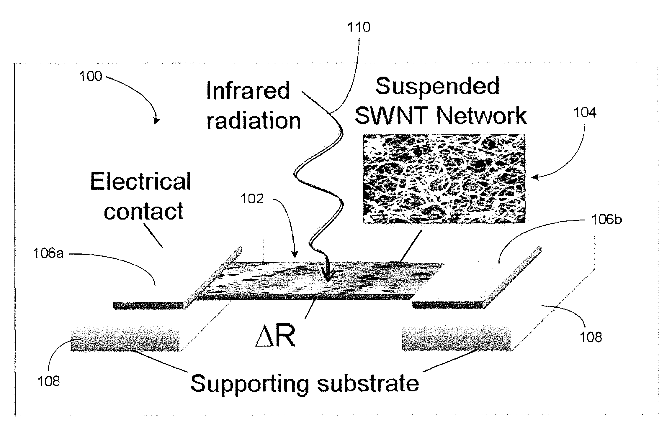
[0034]The present disclosure generally relates to carbon nano structures. In some embodiments, such nano structures can be utilized as to form detector elements. In some embodiments, such nano structures can include carbon nanotube structures. In some embodiments, such carbon nanotube structures can include a plurality of single-walled carbon nanotubes (SWNTs) arranged in a network so as to allow receiving of incident energy and / or radiation power and respond in a bolometric manner. For the purpose of description, “incident energy” and “incident radiation power” may be used interchangeably. For the purpose of description, “bolometric” will be understood to mean a change in temperature in the SWNT network in response to at least a partial absorption of the incident radiation power. In some embodiments, such temperature change can be measured electrically so as to function as a detector.

[0035]Various embodiments of the bolometric based detectors are described in terms of SWNTs. Howeve...


PUM

PropertyMeasurementUnit
thicknessaaaaaaaaaa
temperatureaaaaaaaaaa
pressureaaaaaaaaaa

Abstract

Systems and methods for designing and fabricating carbon nanotube based detectors are disclosed. In some embodiments, one or more sensor elements can be formed from a film of single-walled carbon nanotubes (SWNTs). Bolometric properties of such detectors are disclosed. In some embodiments, the film can be thermally isolated in various ways, such as suspending the film and providing a vacuum environment, to provide the bolometric properties. Various properties of the SWNT films, such as resistivity-dependence on temperature and spectral response, can be obtained by adjusting the dimension and / or composition of the film. Examples of SWNT film formation, detector element fabrication, and array fabrication are disclosed.

Description

STATEMENT OF GOVERNMENT SUPPORT[0001]This invention was made with Government support under Grant Nos. DMEA90-02-2-0216, H94003-04-2-0404, and H94003-05-2-0504 awarded by the Department of Defense. The Government has certain rights in this invention.BACKGROUND[0002]1. Field[0003]The present disclosure generally relates to carbon nanotubes, and more particularly, to systems and methods for designing and fabricating detectors using single-walled carbon nanotubes.[0004]2. Description of the Related Art[0005]Applications for infrared detectors and their 2-dimensional arrays have undergone a dramatic expansion over the past several decades in the areas of thermal imaging. Night vision and other military applications, spectroscopy, infrared astronomy, and failure analysis are some of the applications where infrared detectors are used.[0006]Currently, HgCdTe is a widely used variable band gap semiconductor for infrared (IR) photodetectors. Aside from its toxicity, HgCdTe and corresponding s...

Claims


Application Information

Patent Timeline
Patent Type & Authority Patents(United States)
IPC IPC(8): G01J5/00
CPCG01J5/02G01J5/20G01J5/12G01J5/023
Inventor HADDON, ROBERT C.ITKIS, MIKHAIL E.
Owner RGT UNIV OF CALIFORNIA
Why Eureka
Try Eureka