Biological photometric device

a biochemical and photometric technology, applied in the field of biochemical photometric devices, can solve the problems of spike noise detection method, low s/n noise or mirror noise other than spike noise, and the low s/n noise or mirror noise detection method described in patent document 1 cannot detect the low s/n noise or mirror noise. , to achieve the effect of discriminating low s/n noise or mirror nois

Inactive Publication Date: 2010-05-25
HITACHI LTD
View PDF14 Cites 2 Cited by
  • Summary
  • Abstract
  • Description
  • Claims
  • Application Information

AI Technical Summary

Problems solved by technology

While the spike noise detecting method in the above-described Patent Document 1 is capable of detecting precipitous spike noise generated due to gaps generated in the extremely short time between a body surface of an object and an aperture of optical fibers caused by the movement of the object during the examination or by contingent weight added to optical fibers, there are other kinds of noise such as low S / N noise or mirror noise other than spike noise.
The spike noise detecting method described in Patent Document 1 is not capable of detecting the low S / N noise or mirror noise.

Method used


Image

  • Biological photometric device
  • Biological photometric device
  • Biological photometric device

Examples


first embodiment

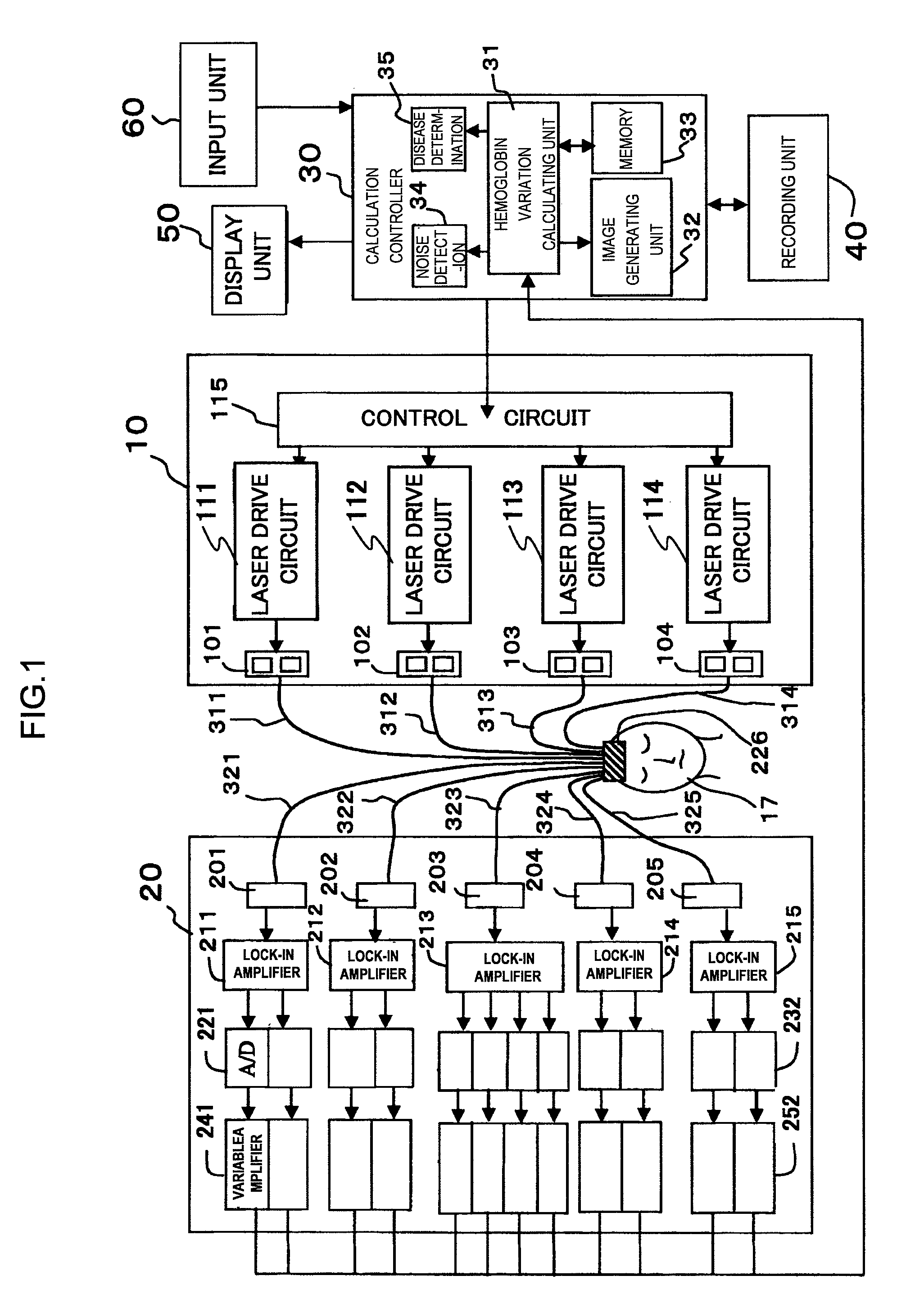
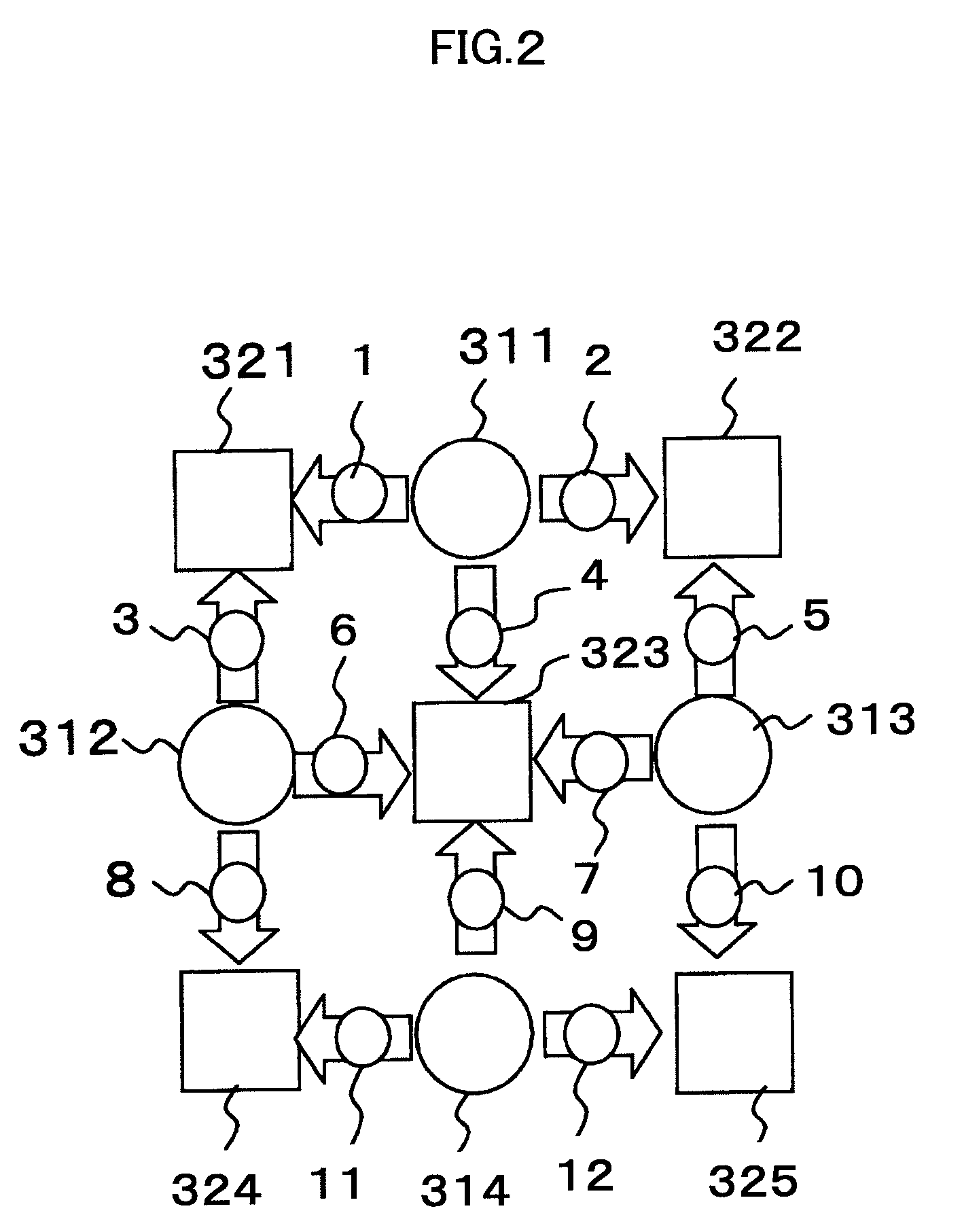
[0033]First, a general configuration of the biological photometric device of the first embodiment related to the present invention will be described using the block diagram of FIG. 1. In the present embodiment, while the device having 12 channels for measuring 12 measure points (channels) 1˜12 are illustrated in FIGS. 1 and 2 and a display example of the device having 24 channels are illustrated in FIGS. 4, 11 and 12 for the sake of the convenience in diagrammatic representation, the present invention is applicable to biological photometric devices provided with an arbitrarily numbers of measurement channels.

[0034]The biological photometric device of the present invention has light-irradiating module 10, light-detecting module 20 and calculation controller 30 comprising CPU, and recording unit 40 for storing obtained data, display unit 50 and input unit 60 for receiving commands from an operator are connected to calculation controller 30 as shown in FIG. 1. In the above-described co...

second embodiment

[0071]Next, the biological photometric device related to the present invention will be described.

[0072]In the biological photometric device of the second embodiment, noise detecting unit 34A has a function for generating the hemoglobin variation signal waveforms of the channel (measurement point) determined as noise, by interpolation calculation from signal waveforms around the channel thereof.

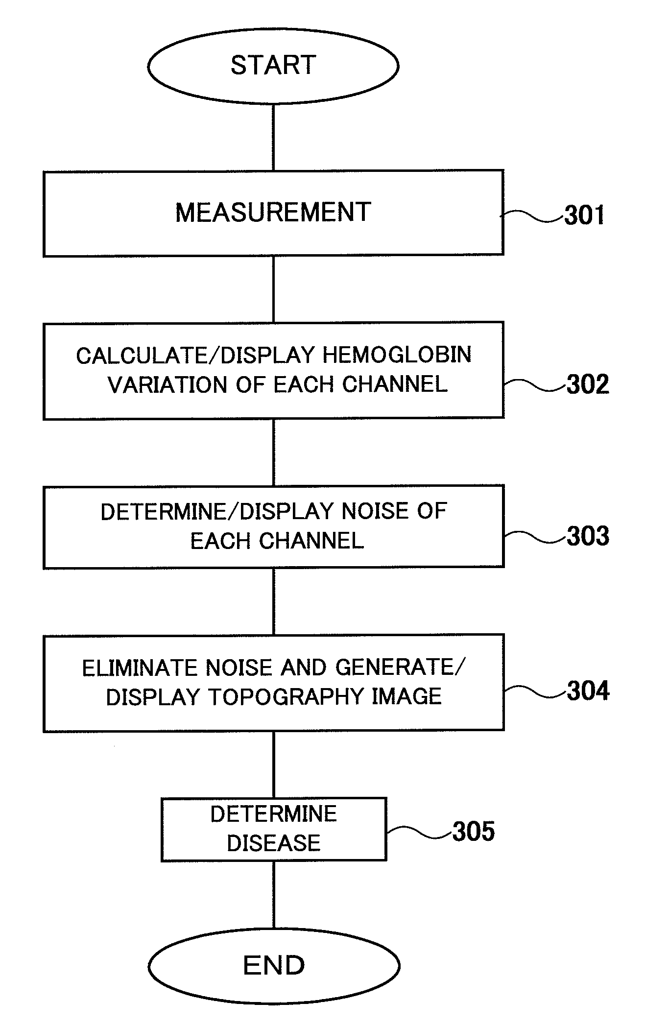
[0073]In step 303 of FIG. 13, noise detecting unit 34A generates a topography image after executing noise detection and display of the detection result in the same manner as the first embodiment, and performs display for asking the operator whether to generate the signal waveforms of the noise channel by interpolation calculation or not, before generating the topography and displaying it to display 50.

[0074]In the case the operator instructs execution of interpolation in response to the above-mentioned display, oxygenated hemoglobin variation or deoxygenated hemoglobin variation of the noise c...


PUM

PropertyMeasurementUnit
wavelengthaaaaaaaaaa

Abstract

A biological photometric device includes a light irradiating unit for irradiating an object to be examined with light having a predetermined wavelength and sympathizing with oxygenated hemoglobin and deoxygenated hemoglobin through an optical fiber, a light detecting unit for detecting and amplifying light passing through a detecting optical fiber and the object as detected signals, a signal processing unit adapted for computing hemoglobin time change information based on oxygenated hemoglobin, deoxygenated hemoglobin and total hemoglobin in the object from the detected signals light detecting unit, and including a noise detector for arithmetically processing the detected signals and determining / detecting whether the time change information is noise attributed to the presence of obstacles to passing of light between the object and the end face of the optical fiber or noise attributed to the damage to the light irradiating unit, and a display unit for displaying the noise signals.

Description

TECHNICAL FIELD[0001]The present invention relates to a biological photometric device for measuring information in a living body by irradiating light to the inside of the living body and receiving the light reflected or scattered in the living body.TECHNICAL BACKGROUND[0002]A biological photometric device is capable of measuring blood circulation, hemodynamics or variation of hemoglobin quantity in a living body in a simple manner without much restriction or any harm to the body, by irradiating light within the range from a visible light to infrared light to the living body of an object to be examined, and detecting the reflected light and scattered light passed inside of the living body.[0003]The biological photometric device is used, for example, when a head region is the subject for measurement, for identifying activated state of the brain due to hemoglobin alteration in blood inflowing in a blood vessel in the brain upon physiological stimulation being imparted, or local focus o...

Claims


Application Information

Patent Timeline
Patent Type & Authority Patents(United States)
IPC IPC(8): A61B5/1455A61B10/00G01N21/17G01N21/35G01N21/359
CPCA61B5/0059G01N21/4795A61B5/14546A61B5/14553
Inventor KAWASAKI, SHINGOTANAKA, NAOKI
Owner HITACHI LTD
Why Eureka
Try Eureka