
Audio splice process for digital Ad insertion

a digital ad and audio splicing technology, applied in the field of digital broadcast signal processing, can solve the problems of accumulative errors, audio distortion, complex splicing, etc., and achieve the effect of avoiding accumulative errors, and avoiding underflow or overflow

Inactive Publication Date: 2010-05-25
GOOGLE TECHNOLOGY HOLDINGS LLC
View PDF11 Cites 9 Cited by
  • Summary
  • Abstract
  • Description
  • Claims
  • Application Information

AI Technical Summary

Benefits of technology

[0009]An object of the present invention is to provide for audio splicing (insertion) of an Ad audio stream in the compressed domain, where variable early delivery of the Ad audio stream and variable bit rate are allowed, without creating audio distortion, glitches, or other digital artifacts or errors, in the resultant audio stream.
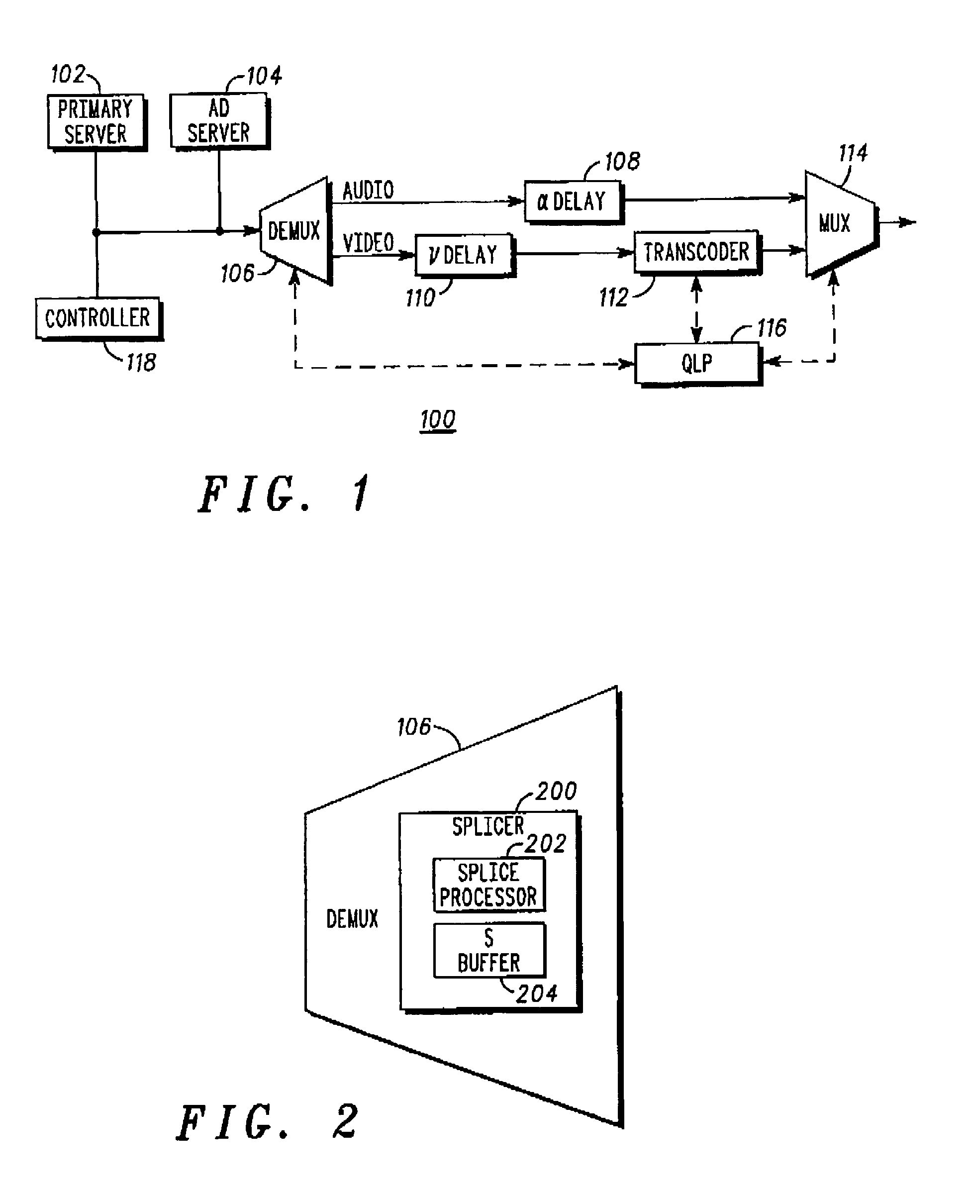
[0010]In order to achieve this objective, as well as others which will become apparent in the disclosure below, the present invention provides for a splice processor which manipulates the audio decoder buffer fullness, in a receiver (end-user) device, to avoid underflow or overflow without repacketizing the audio packets. The present invention also avoids altering the audio decoder buffer fullness of the primary channel after the insertion of the Ad audio stream to avoid accumulative error.
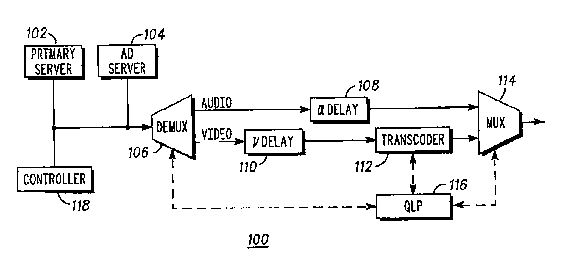
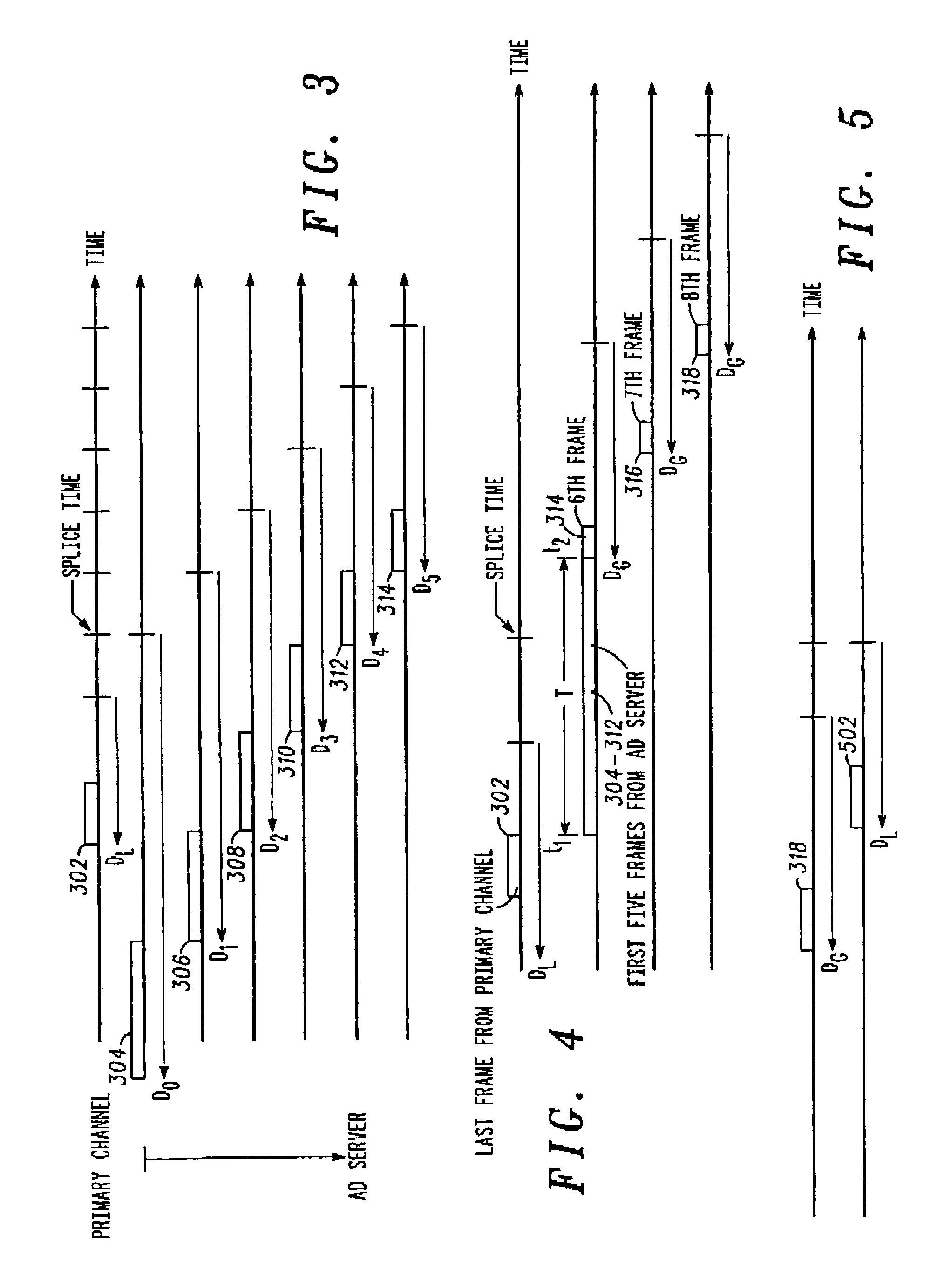
[0011]In an exemplary embodiment, the present invention comprises a system and method to establish a target Ad audio stream frame transmission delay (“Ad frame delay”) relative to the pre-determined presentation time, and to maintain the target Ad frame delay throughout the Ad. More specifically, the present invention provides for (1) manipulating the audio decoder buffer fullness to avoid underflow or overflow without repacketizing the audio packets; (2) avoiding altering the audio decoder buffer fullness of the primary channel after the insertion to avoid accumulative error; (3) establishing an Ad frame delay at the splice time by buffering the first five frames of the Ad audio stream from the Ad server before the splice time and transmitting them from the delay buffer in a shorter time span; and (4) maintaining the Ad frame delay throughout the transmission of Ad audio stream based upon, in part, the PTS, which will prevent accumulative error and will be fault resilient to bit stream errors.
[0012]Thus, the present system and method provides for a splice processor which uses the Ad frame delay to manipulate the audio decoder buffer fullness to avoid underflow or overflow without repacketizing the audio packet, thus avoiding audio distortion.

Problems solved by technology

With the advent of digital broadcast signals, such splicing has become more complex because digital video and audio streams are conventionally separate and distinct streams, prior to modulation to end users.
Further, of the two types of streams (audio and video), audio is the most problematic, as discussed below.
The above approach, however, is prone to producing unpredictable results such as audio distortion due to the buffer underflow in the audio decoder buffer.
However, the Ad audio stream is delivered by the Ad server too early relative to the splice time.
Then, when the Ad audio stream is presented to the end-user in accordance with the PTS, the dropped packets will obviously cause all types of undesirable audio distortion.
Unfortunately, this early delivery is quite common in conventional digital broadcast systems.
However, this will only prevent the audio buffer from overflowing if the audio buffer is allowed to empty prior to the start of the Ad server audio stream.
Unfortunately, the 300 millisecond (or greater) early delivery is too large for a fixed bit rate audio stream if decoder buffer underflow is not allowed prior to the start of the Ad audio stream.
Thus, earlier delivery of an Ad audio stream of 300 milliseconds is far above the maximum frame transmission delay and as a result, the audio decoder buffer may overflow.
Further, if the Ad audio stream is delayed by a fixed time to avoid the overflow, an underflow may occur, because the start of the audio stream is transmitted too slow.
The above described audio decoder buffer underflow and overflow results in audio distortion.

Method used


Image

  • Audio splice process for digital Ad insertion
  • Audio splice process for digital Ad insertion
  • Audio splice process for digital Ad insertion

Examples


Embodiment Construction

[0019]The following references are hereby incorporated by reference in their entireties: (1) Vincent Liu, “Splice Operation for ASPEN”, Jan. 8, 2002; (2) GIC-616, U.S. patent application Ser. No. 09 / 872,783, “Splice Point Processing in an MPEG-2 Multiplexer”; (3) SCTE DVS380, “Digital Program Insertion Splicing API”; and (4) ISO / IEC JTC1 / SC29 / WG11 “CODING OF MOVING PICTURES AND ASSOCIATED AUDIO” (a commonly known standard), all of which have been previously filed with U.S. Provisional Patent Application No. 60 / 489,825.

[0020]Although the present invention will be illustrated below primarily in conjunction with MPEG-2 transport streams, the present invention is more broadly applicable to MPEG-2 program streams as well as to packet-based data streams generated in accordance with standards other than MPEG-2. These other standards include asynchronous transfer mode (ATM), transmission control protocol / Internet protocol (TCP / IP), and frame relay. The term “transport stream” or “stream” as...


PUM


Abstract

A system and method for audio splicing (insertion) of an Ad audio stream in the compressed domain, where variable early delivery of the Ad audio stream and variable bit rate are allowed, without creating audio distortion, glitches, or other digital artefacts or errors, in the resultant audio stream is disclosed. The present system and method provides for a splice delay buffer which delays the first five Ad audio frames until transmission of the last frame of the primary audio stream, but before the splice time. Subsequent Ad audio frames are delayed by a fixed amount, where the fixed amount is greater than the frame delay of the primary audio stream, to allow for ease of splice back to the primary audio stream.

Description

CROSS-REFERENCE TO RELATED APPLICATION[0001]This application is related to U.S. Provisional patent application 60 / 489,825, filed on Jul. 24, 2003, from which priority is claimed, and which is herein incorporated by reference in its entirety.FIELD OF THE INVENTION[0002]The present invention relates to the processing of digital broadcast signals. More specifically, the present invention relates to the splicing of a second transport stream into a first transport stream to enable the insertion of an advertisement (“Ad”), local program, or the like.BACKGROUND OF THE INVENTION[0003]Splicing video and audio has been a practice used for decades in the video broadcasting industry. Splicing allows for advertisements, or other locality specific content, to be inserted in the broadcast stream for consumption by a discrete (often regional) audience. With the advent of digital broadcast signals, such splicing has become more complex because digital video and audio streams are conventionally separ...

Claims


Application Information

Patent Timeline
Patent Type & Authority Patents(United States)
IPC IPC(8): G06F17/00H04N9/74H04N7/025H04N7/10H04N7/16H04N7/24
CPCH04N21/2335H04N21/23424H04N21/812H04N21/8106H04N21/44016
Inventor CHEN, JINGYANGNEMIROFF, ROBERT S.
Owner GOOGLE TECHNOLOGY HOLDINGS LLC
Learn More