Method and equipment for realizing data transmission via PTN

A technology of data transmission and equipment, applied in the field of communication, can solve problems such as performance degradation, long transmission delay, large buffer memory, etc., and achieve the effect of avoiding overflow and underflow, eliminating delay and jitter

Active Publication Date: 2014-07-02
ALCATEL LUCENT SHANGHAI BELL CO LTD
View PDF7 Cites 0 Cited by
  • Summary
  • Abstract
  • Description
  • Claims
  • Application Information

AI Technical Summary

Problems solved by technology

However, using a public network will cause network transmission delay (delay) and jitter (jitter)
For example, on the Ir interface, the Ir service is a time-critical service. If the figure 1 The schematic diagram of the network connecting BBU (Indoor Base Band Unit, Building Base Band Unit) and RRU (Radio Radio Unit, Remote Radio Unit) based on IroPTN (Ir over PTN) instead of Ir interface, where PTP (Precision Time Protocol1) is accurate Clock protocol, syncE is synchronous Ethernet, in the RAN network, if the de-jitter solution is not adopted, it will cause performance degradation
Traditional de-jitter methods have the following defects: consume a large amount of buffer memory, long transmission delay, no protection against buffer overflow (overflow) and underflow (underflow), etc.

Method used


Image

  • Method and equipment for realizing data transmission via PTN
  • Method and equipment for realizing data transmission via PTN
  • Method and equipment for realizing data transmission via PTN

Examples


Embodiment Construction

[0025] The present invention will be described in further detail below in conjunction with the accompanying drawings.

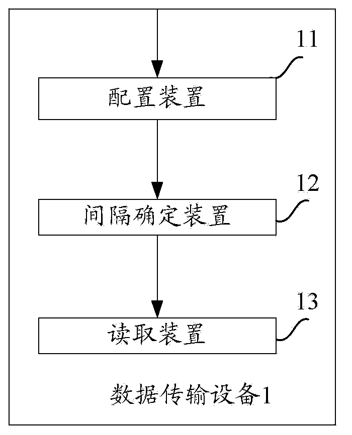
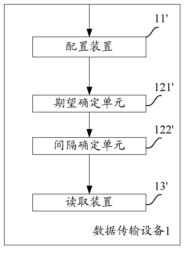
[0026] figure 2 Shown is a data transmission device 1 for data transmission via a PTN according to an aspect of the present invention, wherein the data transmission device 1 comprises configuration means 11 , interval determination means 12 and reading means 13 . Specifically, the configuring device 11 configures the packet buffering device according to the network traffic model corresponding to the PTN; the interval determining device 12 determines the reading interval information of the buffered packets in the packet buffering device, wherein the buffered packets are between the BBU and the RRU The reading device 13 reads the corresponding buffered packets from the packet buffering device according to the reading interval information for transmission between the BBU and the RRU. Here, the data transmission device 1 includes but is not limited to any elect...


PUM


Abstract

The invention aims to provide a method and equipment for realizing data transmission via a PTN. Specifically, according to a network flow model corresponding to the PTN, a packet buffering device is configured; reading interval information of buffered packets in the packet buffering device is determined, and the buffered packets are transmitted between a BBU and an RRU; and according to the reading interval information, a corresponding buffered packet is read from the packet buffering device so to be transmitted between the BBU and the RRU. Compared with the prior art, according to the method in the invention, by configuring the packet buffering device is configured and determining the reading interval information of the buffered packets in the packet buffering device, the corresponding buffered packet is read from the packet buffering device based on the reading interval information so as to be transmitted between the BBU and the RRU, thereby realizing self-adaptive adjustment of a reading time interval of the buffered packets in the packet buffering device, while eliminating delay and jitter caused by the PTN, preventing overflow and underflow of the packet buffering device, and ensuring stability of a network system.

Description

technical field [0001] The present invention relates to the field of communication technology, in particular to a technology for realizing data transmission via PTN. Background technique [0002] In a new RAN (Radio Access Network, Radio Access Network) structure, it is a new technical trend to use a public network, such as a PTN (Packet Transport Network, Packet Transport Network) instead of a dedicated optical network. However, using a public network will cause network transmission delay (delay) and jitter (jitter). For example, on the Ir interface, the Ir service is a time-critical service. If the figure 1 The schematic diagram of the network connecting BBU (Indoor Base Band Unit, Building Base Band Unit) and RRU (Radio Radio Unit, Remote Radio Unit) based on IroPTN (Ir over PTN) instead of Ir interface, where PTP (Precision Time Protocol1) is accurate The clock protocol, syncE is synchronous Ethernet, in the RAN network, if a de-jitter solution is not adopted, it will ...

Claims


Application Information

Patent Timeline
IPC IPC(8): H04L12/801
Inventor 李明张旭颜锋华孙犀利
Owner ALCATEL LUCENT SHANGHAI BELL CO LTD
Why Eureka
Try Eureka