Direct injection spark ignition internal combustion engine and fuel injection method for same

a technology of spark ignition and internal combustion engine, which is applied in the direction of electric control, machines/engines, mechanical equipment, etc., can solve the problems of injected fuel vaporization, and achieve the effect of efficiently intensifying tumble flow

Inactive Publication Date: 2010-06-01
TOYOTA JIDOSHA KK
View PDF38 Cites 4 Cited by
  • Summary
  • Abstract
  • Description
  • Claims
  • Application Information

AI Technical Summary

Benefits of technology

[0011]When the detected or estimated temperature of the surface of the cylinder bore wall is lower than the predetermined temperature, the possibility that the injected fuel evaporates from the surface of the cylinder bore wall is low. Further, the lower the detected or estimated temperature of the injected fuel, the more unlikely it is for the injected fuel to vaporize while moving in the cylinder and thus the larger the amount of fuel that reaches on the surface of the cylinder bore wall. To counter this, in the direct injection spark ignition internal combustion engine according to the second aspect of the invention, when intensifying a tumble flow using the fuel injected at a time near the intake stroke bottom dead center, if the detected or estimated temperature of the surface of the cylinder bore wall is lower than the predetermined temperature, the thrust force of the injected fuel is decreased such that it decreases as the detected or estimated temperature of the injected fuel decreases. This minimizes the possibility that the injected fuel will reach the surface of the cylinder bore wall and thus the possibility of engine oil dilution that may occur when the temperature of the surface of the cylinder bore wall is low. Further, the lower the detected or estimated temperature of the injected fuel, the more unlikely it is for the injected fuel to vaporize while moving in the cylinder. Therefore, even if the thrust force of the injected fuel is decreased as described above, it is still possible to intensify the tumble flow sufficiently by that injected fuel.
[0017]According to the fifth aspect of the invention, the temperature of the injected fuel can be decreased by cooling the fuel injector using an air flow.
[0023]The fuel injected in the direction substantially parallel to the plane parallel to the tumble flow intensifies the tumble flow more effectively than the fuel injected in the direction crossing the plane parallel to the tumble flow does. According to the eighth aspect of the invention, therefore, the tumble flow can be efficiently intensified without increasing the entire amount of the injected fuel by making the thrust force of the fuel injected in the direction substantially parallel to the plane parallel to the tumble flow larger than the fuel injected in the direction crossing the plane parallel to the tumble flow. Further, because the fuel is injected in a plurality of directions, the fuel can easily spread throughout the entire area in the cylinder, and therefore the tumble flow can be efficiently intensified.
[0025]According to the ninth aspect of the invention, because the thrust force of fuel injected from the fuel injector is increased when the amount of intake air that is introduced per unit time during the fuel injection period is large than when the same amount is small, it is possible to avoid a situation where the injected fuel penetrates the tumble flow and thus most of the kinetic energy is not utilized to intensify the tumble flow. Thus, the tumble flow can be efficiently intensified without increasing the entire amount of the injected fuel.

Problems solved by technology

Further, the lower the detected or estimated temperature of the injected fuel, the more unlikely it is for the injected fuel to vaporize while moving in the cylinder and thus the larger the amount of fuel that reaches on the surface of the cylinder bore wall.
Further, the lower the detected or estimated temperature of the injected fuel, the more unlikely it is for the injected fuel to vaporize while moving in the cylinder.

Method used


Image

  • Direct injection spark ignition internal combustion engine and fuel injection method for same
  • Direct injection spark ignition internal combustion engine and fuel injection method for same
  • Direct injection spark ignition internal combustion engine and fuel injection method for same

Examples


Embodiment Construction

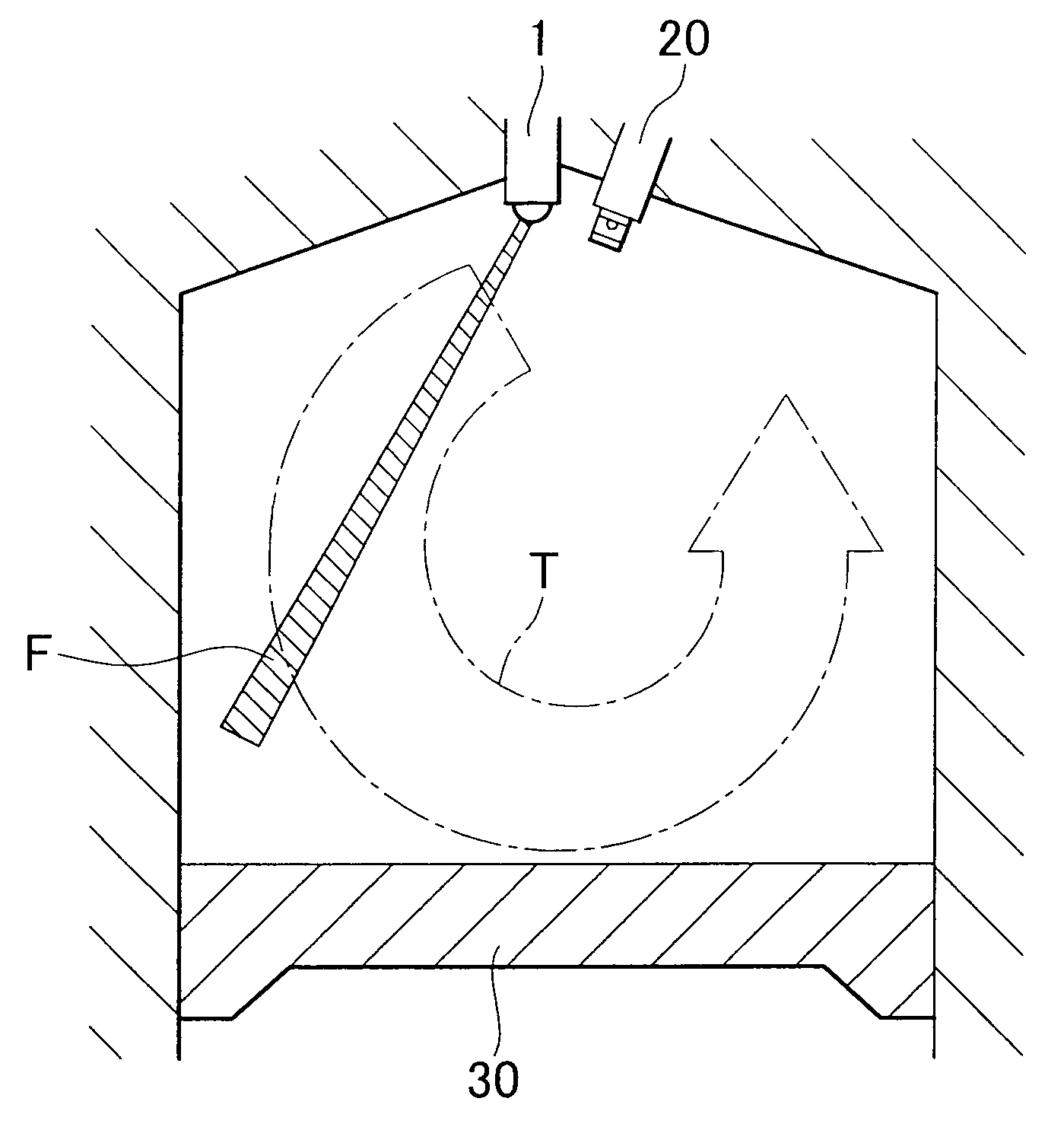
[0037]FIG. 1 is a vertical cross-sectional view schematically showing the structure of each cylinder of a direct injection spark ignition internal combustion engine according to the first exemplary embodiment of the invention. Specifically, FIG. 1 shows the state near the bottom dead center on an intake stroke (will be referred to as “intake stroke bottom dead center”) that corresponds to the time of fuel injection for homogenous combustion. Referring to FIG. 1, a fuel injector 1 is provided at substantially the center of the upper area of the cylinder to inject fuel directly into the cylinder. Also, in the cylinder, an ignition plug 20 is provided near the fuel injector 1 on the intake valve side thereof and a piston 30 is provided. Although not shown in the drawings, a pair of intake valves are provided on the right side above the cylinder and a pair of exhaust valves are provided on the left side above the cylinder.

[0038]In the direct injection spark ignition internal combustion ...


PUM


Abstract

A direct injection spark ignition internal combustion engine includes a fuel injector for directly injecting fuel into a cylinder and intensifies a tumble flow using the fuel injected into the cylinder bore at a time near an intake stroke bottom dead center during homogenous combustion. The thrust force of the fuel injected from the fuel injector is set to intensify the tumble flow based on at least one of the state of the combustion chamber, the temperature of the injected fuel, and the orientation of the injection hole.

Description

BACKGROUND OF THE INVENTION[0001]1. Field of the Invention[0002]The invention relates to a direct injection spark ignition internal combustion engine and a fuel injection method for the same.[0003]2. Description of the Related Art[0004]Homogenous combustion is performed by forming a homogenous air-fuel mixture in each cylinder and igniting it at the ignition time that comes at the end of each compression stroke. During such homogenous combustion, a tumble flow is created in the cylinder and the created tumble flow is maintained active until the ignition time at the end of the compression stroke. By doing so, the movement of air-fuel mixture can be maintained until ignition, and this air-fuel mixture movement accelerates the combustion speed, whereby the homogenous combustion progresses in a good condition.[0005]For example, Japanese Patent Application Publication JP-A-2005-180247A proposes a direct injection spark ignition internal combustion engine that has an intake flow control v...

Claims


Application Information

Patent Timeline
Patent Type & Authority Patents(United States)
IPC IPC(8): F02B31/00F02M7/28
CPCF02B23/10F02D35/025F02M53/02F02M61/161F02M69/045F02B23/101F02B2023/102F02B2023/106F02D41/047Y02T10/125F02D2200/0606F02D2250/31F02D2041/0015Y02T10/12F02D41/30F02M53/04
Inventor ASHIZAWA, TAKESHI
Owner TOYOTA JIDOSHA KK
Why Eureka
Try Eureka