Belt-driven continuously variable transmission

a continuously variable transmission and belt drive technology, which is applied in the direction of gearing, gearing elements, hoisting equipments, etc., can solve the problems of inability excessive consumption of energy to increase the rotational speed of the transmission motor, and difficulty or impossible to carry out speed change operation, etc., to achieve the effect of increasing the downshifting speed, increasing the friction between the driving belt and the conical surface of the driven pulley, and increasing the roughness of the driving

Inactive Publication Date: 2013-11-14
TOYOTA JIDOSHA KK
View PDF6 Cites 5 Cited by
  • Summary
  • Abstract
  • Description
  • Claims
  • Application Information

AI Technical Summary

Benefits of technology

This patent is about a new type of transmission for vehicles that can change gears even when the vehicle is stopped. The transmission uses a special belt that can slide on the surfaces of the gear teeth in the transmission. This allows for a smooth and reliable gear change, even when the vehicle is moving or stopped. The belt is reinforced with metal blocks to increase its strength. This new design also improves the speed at which the transmission can change gears and reduces the force applied to the transmission components, which improves durability.

Problems solved by technology

Therefore, if the nonmetallic belt thus structured is used in the continuously variable transmission, it is difficult or impossible to carry out a speed change operation under the situation that rotational speeds of the pulleys are low or the pulleys are not rotated.
In this case, however, a speed change operation cannot be carried out if the pulleys are not rotated.
In this situation, however, energy has to be consumed excessively to increase the rotational speed of the transmission motor.
As a result, fuel economy of the vehicle may be degraded.
In addition, a thrust force for changing a groove width of the pulleys may be increased excessively large with an increase in a rotational speed of a speed change motor, and a durability of the driving belt may be degraded by the clamping force thus increased excessively.

Method used


Image

  • Belt-driven continuously variable transmission
  • Belt-driven continuously variable transmission
  • Belt-driven continuously variable transmission

Examples


Embodiment Construction

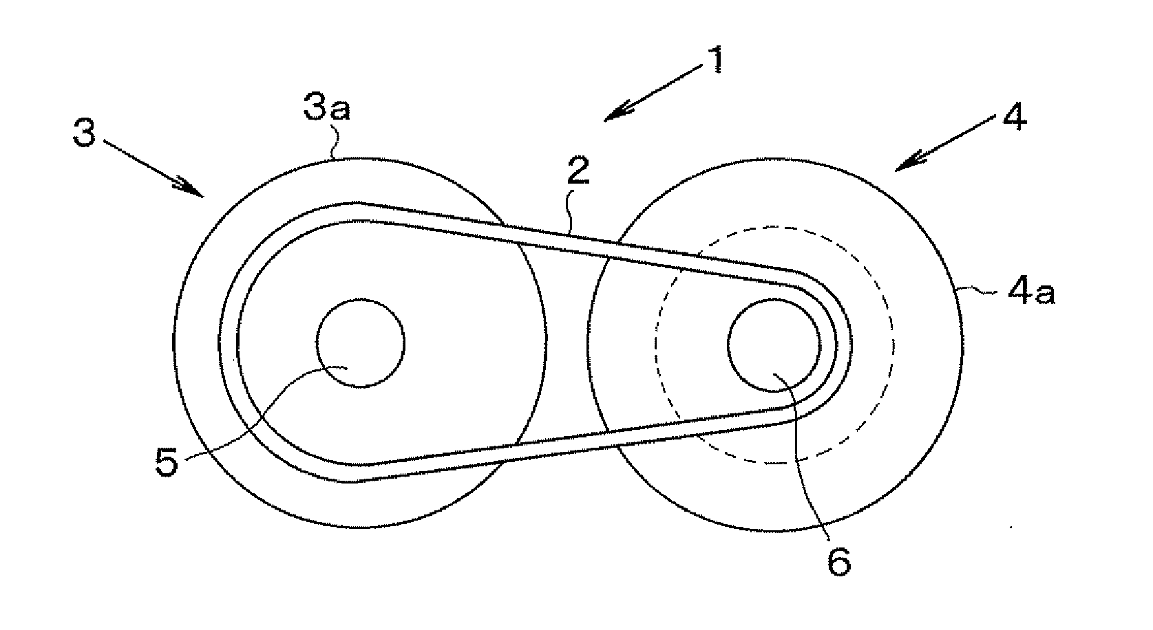
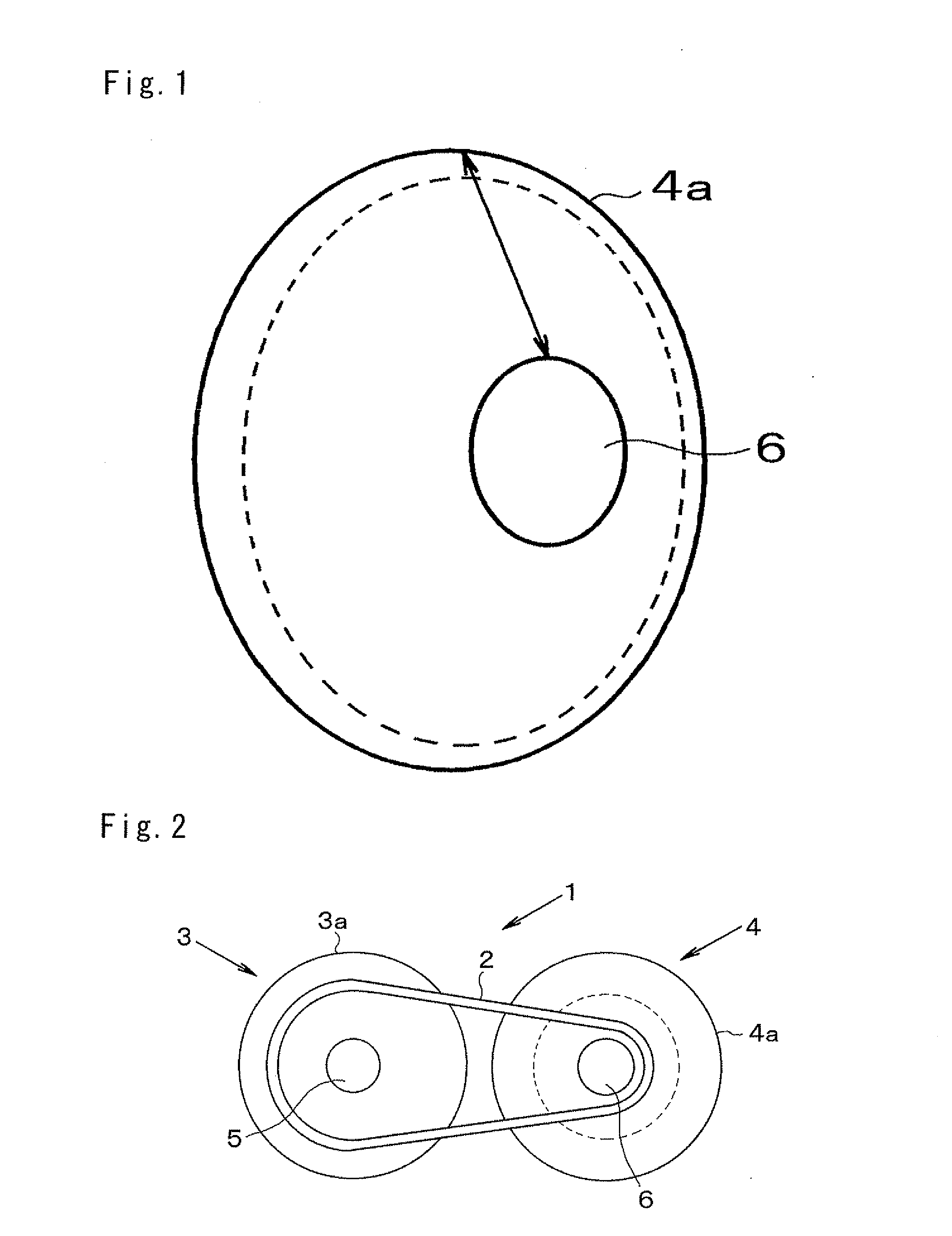
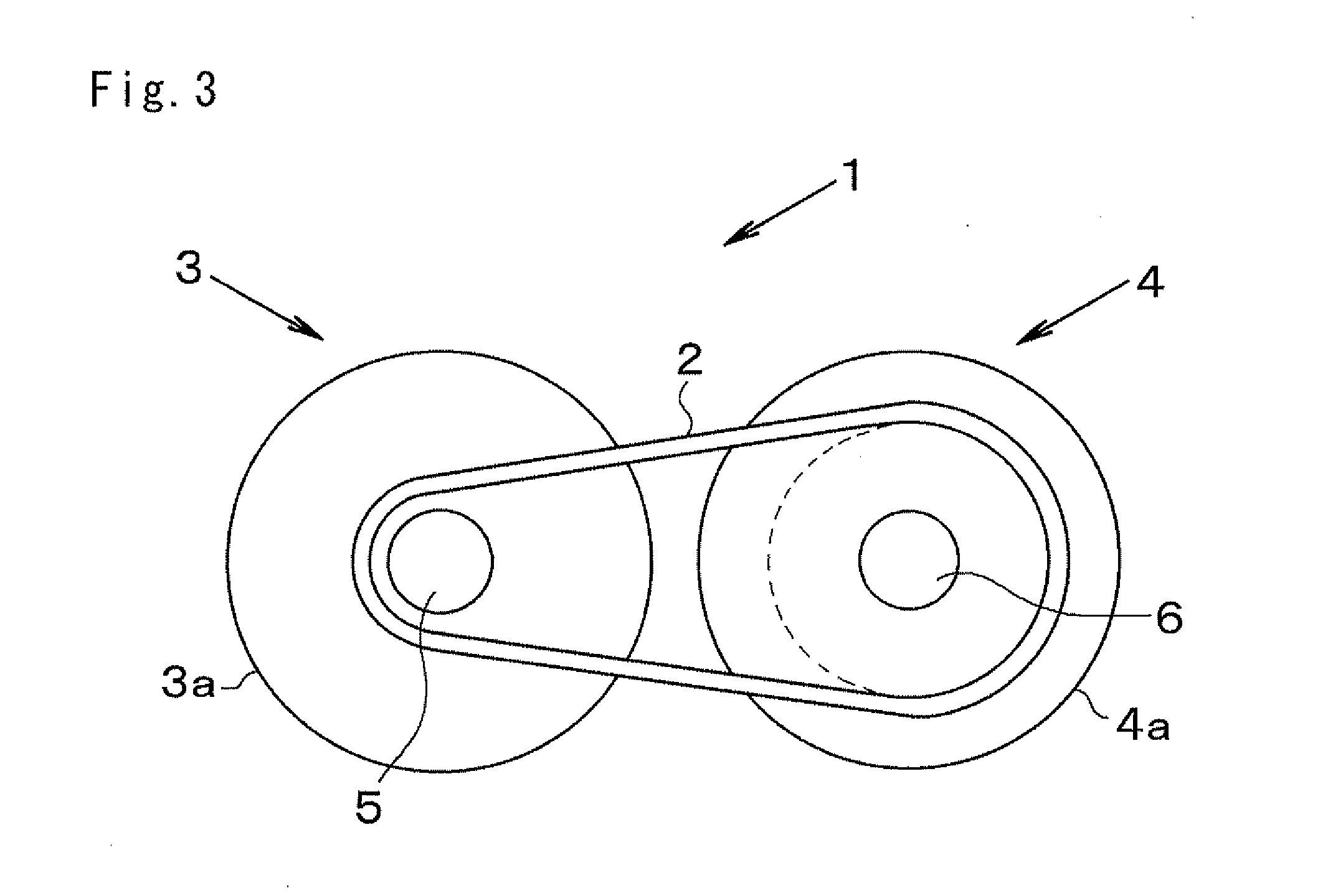
[0024]Next, a preferred example of the present invention will be explained hereinafter. The present invention relates to a belt-driven continuously variable transmission adapted to change a speed ratio continuously by altering an effective diameter position of a driving belt running on a drive pulley and a driven pulley. In the belt-driven continuously variable transmission, the effective diameter position of the driving belt is displaced by altering a width of a V-shaped groove (as will be called a belt groove hereinafter) formed between sheaves of each pulley. Each drive and driven pulley is comprised of a pair of sheaves (or discs), and the belt groove is formed between conical inner surfaces of those sheaves opposed to each other. One of those sheaves is integrated with a rotary shaft (i.e., a pulley shaft) to serve as a fixed sheave, and the other sheave is fitted onto the rotary shaft in a slidable manner to serve as a movable sheave. Specifically, the movable sheave is allowe...


PUM


Abstract

A belt-driven continuously variable transmission includes a drive pulley, a driven pulley and a driving belt. Each pulley is formed by a fixed sheave integrated with a rotary shaft and a movable sheave fitted onto the rotary shaft in a slidable manner. A belt groove holding a driving belt is formed individually between conical surfaces of the fixed sheave and the movable sheaves being opposed to each other. The belt-driven continuously variable transmission changes a speed ratio continuously by altering an effective diameter of the driving belt by varying the groove width. A non-metallic belt made of resin material is used as the driving belt, and a friction coefficient of a radially inner region of each conical surface of driven pulley is smaller than that in a radially outer region.

Description

TECHNICAL FIELD[0001]The present invention relates to a belt-driven continuously variable transmission for transmitting power through a driving belt applied between a drive pulley and a driven pulley, while varying a speed ratio steplessly by continuously varying an effective diameter position of the driving belt.BACKGROUND ART[0002]The belt-driven continuously variable transmission of this kind is adapted to transmit power by a frictional force between the driving belt and the pulleys holding the driving belt therebetween. The belt-driven continuously variable transmission thus structured changes a speed ratio thereof continuously by varying a groove width between a drive pulley and a driven pulley thereby altering the effective diameter position of the driving belt. The driving belts are categorized into a metal belt formed by fastening a plurality of metal pieces called an element or a block by a steel belt, and a nonmetallic belt formed mainly of rubber or resin.[0003]Generally,...

Claims


Application Information

Patent Timeline
Patent Type & Authority Applications(United States)
IPC IPC(8): F16H9/18
CPCF16G5/16F16H55/56F16H9/18F16G5/166
Inventor SANO, TOSHINARIIJICHI, AKIRASAITO, TATSUYA
Owner TOYOTA JIDOSHA KK
Why Eureka
Try Eureka