Film comprising individual anchored filaments

a technology of individual filaments and loops, applied in the direction of snap fasteners, synthetic resin layered products, wood working apparatus, etc., can solve the problems of high cost, complicated production methods of female sections, and particularly costly female sections obtained, and achieve low cost, high rate, and soft handle

Inactive Publication Date: 2010-06-01
APLIX INC
View PDF17 Cites 6 Cited by
  • Summary
  • Abstract
  • Description
  • Claims
  • Application Information

AI Technical Summary

Benefits of technology

[0003]The present invention relates to a method of producing a female section of a fastening which allows a female fastening section to be obtained at a very low cost on the one hand and which allows production thereof at a high rate on the other hand. Besides, the use of thin filaments also allows a very soft handle because the filament, being extruded, is in a material state of weak orientation which allows great suppleness and softness. Good readability of the designs which may be printed below the film is also obtained.
[0008]The production method is thus particularly rapid and allows large-scale production of female loop sections for fastenings, particularly in the field of training pants.
[0024]According to an advantageous embodiment, the filaments are crimped or textured, thus enhancing the hold of the hooks by reason of the local rippling on the outer surface of the filaments themselves. Each thus crimped or textured filament is more easily distinguished from its neighbours.

Problems solved by technology

The production method of these female sections is complicated to implement, particularly by reason of the fact that a soldering stage and a film retraction stage are provided for forming the loops.
Thus, the female section obtained is particularly costly.
In fact, an elastic material (we are not even talking about a thermo-retractable material) is a costly material on the one hand and on the other hand the filaments, in order to withstand the different operations (soldering and stretching), are filaments with large diameters, particularly greater than 10 decitex, thus resulting in a high cost.

Method used


Image

  • Film comprising individual anchored filaments
  • Film comprising individual anchored filaments
  • Film comprising individual anchored filaments

Examples


Embodiment Construction

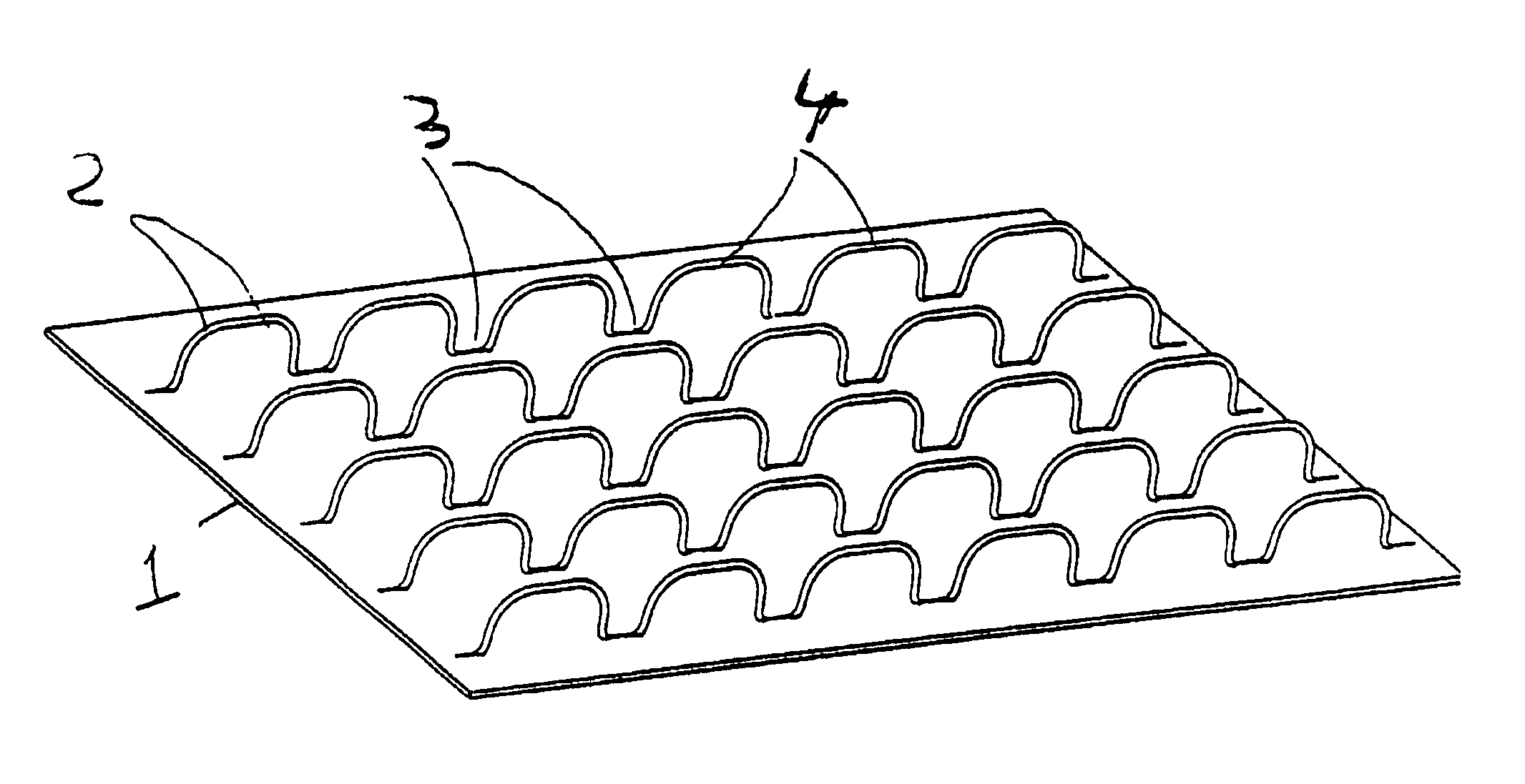
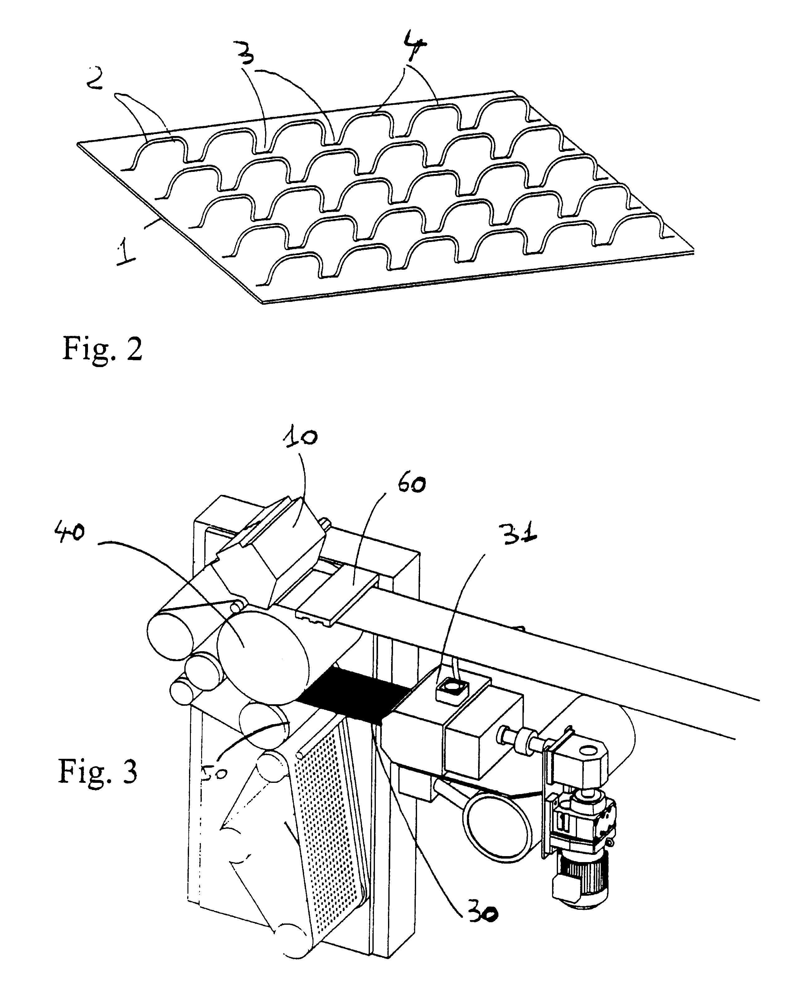
[0030]A loop section according to the invention can be seen in FIG. 2. This loop section is constituted by a film 1 made of non-elastic and non-thermo-retractable material, whereby filaments 2 are anchored in the film 1. The filaments 2 are arranged in rows on the film 1. Each filament 2 is constituted by a succession of hollow and boss sections, namely hollow sections or anchoring sections 3 and boss sections or sections forming loops 4. In the anchoring sections 3 the filaments are anchored in the plastic material of the film. In particular they are anchored partially in the plastic material of the film. The filaments have a titre equal to 5.5 decitex. Preferably, this title is strictly less than 10 decitex.

[0031]Each row of loops in the longitudinal direction in the drawing is spaced apart from the neighbouring rows by a distance equal to and preferably greater than 0.15 mm, particularly between 0.05 and 0.5 mm. This inter-row distance can vary from one row to another, particular...


PUM

PropertyMeasurementUnit
distanceaaaaaaaaaa
thicknessaaaaaaaaaa
thicknessaaaaaaaaaa

Abstract

The invention relates to a film comprising individual anchored filaments. More specifically, the invention relates to the female part of a hook-and-loop self-adhering support, comprising a plastic film and independent filaments which are fixed to one of the faces of the film. The invention is characterized in that part of the length of each filament is anchored to the plastic film, while the remainder thereof is disposed at a distance from the film, such as to form loops. According to the invention, the film is made from a non-elastic and non-heat-shrinkable material and the filaments have a count of less than 10, preferably less than or equal to 7.7, for example between 2 and 5 decitex.

Description

TECHNICAL FIELD[0001]The present invention relates to a female loop section for a self-gripping hook and loop fastening, intended in particular for use for fastening training pants. The present invention also relates to a method of producing a female loop section of this type.BACKGROUND ART[0002]Numerous devices and methods are described in patents relating to these female loop sections for hook and loop fastenings and in particular in the field of training pants. Taking into account the production imperatives, it is desirable to make available a female loop section which is as cost-effective as possible and to be able to produce it with the quickest production rate possible. For example the European patent No. 0 289 198 in the name of Procter & Gamble Company discloses a female loop section constituted by a film made of an elastic material and filaments soldered to the film according to a soldering pattern, the soldering being realised in such a way that loops are formed by the fil...

Claims


Application Information

Patent Timeline
Patent Type & Authority Patents(United States)
IPC IPC(8): B32B3/02A44B18/00A61F13/15B27N3/04B29C65/00B32B3/14B32B3/16A61F13/62B29C48/08
CPCA44B18/0011B29C66/836B29C47/0038B29C65/008B29C65/028B29C66/69A61F13/62B29C47/0021B29C47/0057B29C47/0069B29C47/32B29C66/919B29C66/91921B29C66/91933B29K2023/12B29L2009/00B29L2031/4878B29L2031/729B29C66/91411Y10T428/24Y10T24/275Y10T24/27Y10T428/24008Y10T24/2758B29C66/83433A61F13/627B29C66/71B29C66/723B29C48/08B29C48/001B29C48/0018B29C48/0023B29C48/35Y10T428/23957Y10T428/23986B29K2077/00B29K2067/00B29K2023/06
Inventor DUCAUCHUIS, JEAN-PIERRE
Owner APLIX INC
Why Eureka
Try Eureka