Split-coil magnet arrangement with improved mechanical construction

a technology of mechanical construction and coil section, applied in the direction of superconducting magnets/coils, using reradiation, magnetic materials, etc., can solve the problem of space-saving invention of magnet arrangement, and achieve the effect of less mass, strong magnetic field, and strong forces on the coil section system

Inactive Publication Date: 2010-06-01
BRUKER SWITZERLAND AG
View PDF11 Cites 7 Cited by
  • Summary
  • Abstract
  • Description
  • Claims
  • Application Information

AI Technical Summary

Benefits of technology

[0015]Whereas in the known arrangements the coil section systems are connected inside a container by means of a rigid structure and thus only a resulting force attracting toward the split acts on the coil systems and therefore also on the containers containing the coil systems, the coil systems and the corresponding containers of the inventive magnet arrangement are locally exposed to forces both acting toward the split and away from the split. The decisive idea of the invention is to arrange structures that withstand both compressive loads and tensile loads in the split. This arrangement permits to support the magnetic forces where they appear. The advantage of the inventive arrangement is that no rigid structure is required inside the container to interconnect the coil section systems in order to support the magnetic forces in the coil systems. The inventive mechanical structure is therefore not exposed to any torque acting inside the coil section systems due to the magnetic forces, but is only subject to compressive or tensile loads. This greatly reduces or eliminates the bending forces acting on the mechanical structure. The inventive arrangement therefore requires less material for the mechanical structure to support the magnetic forces. Moreover, the containers can be smaller because rigid structures inside the containers are no longer required. This makes the inventive magnet arrangement space-saving. In particular, the distance between the magnet center and the cryostat floor can be kept small.
[0037]The inventive magnet arrangement is preferably part of an apparatus for neutron scattering, an apparatus for X-ray scattering or an MRI apparatus. The inventive mechanical structure in the split enables the building of a coil configuration in which the forces on the coil section systems are especially high. These forces have until now placed narrow limits on the design of the magnet arrangement. The inventive arrangement permits, in particular, stronger magnetic fields in the working volume and more efficient active stray field shielding, which is a special benefit in the aforementioned applications.

Problems solved by technology

This makes the inventive magnet arrangement space-saving.

Method used


Image

  • Split-coil magnet arrangement with improved mechanical construction
  • Split-coil magnet arrangement with improved mechanical construction
  • Split-coil magnet arrangement with improved mechanical construction

Examples


Embodiment Construction

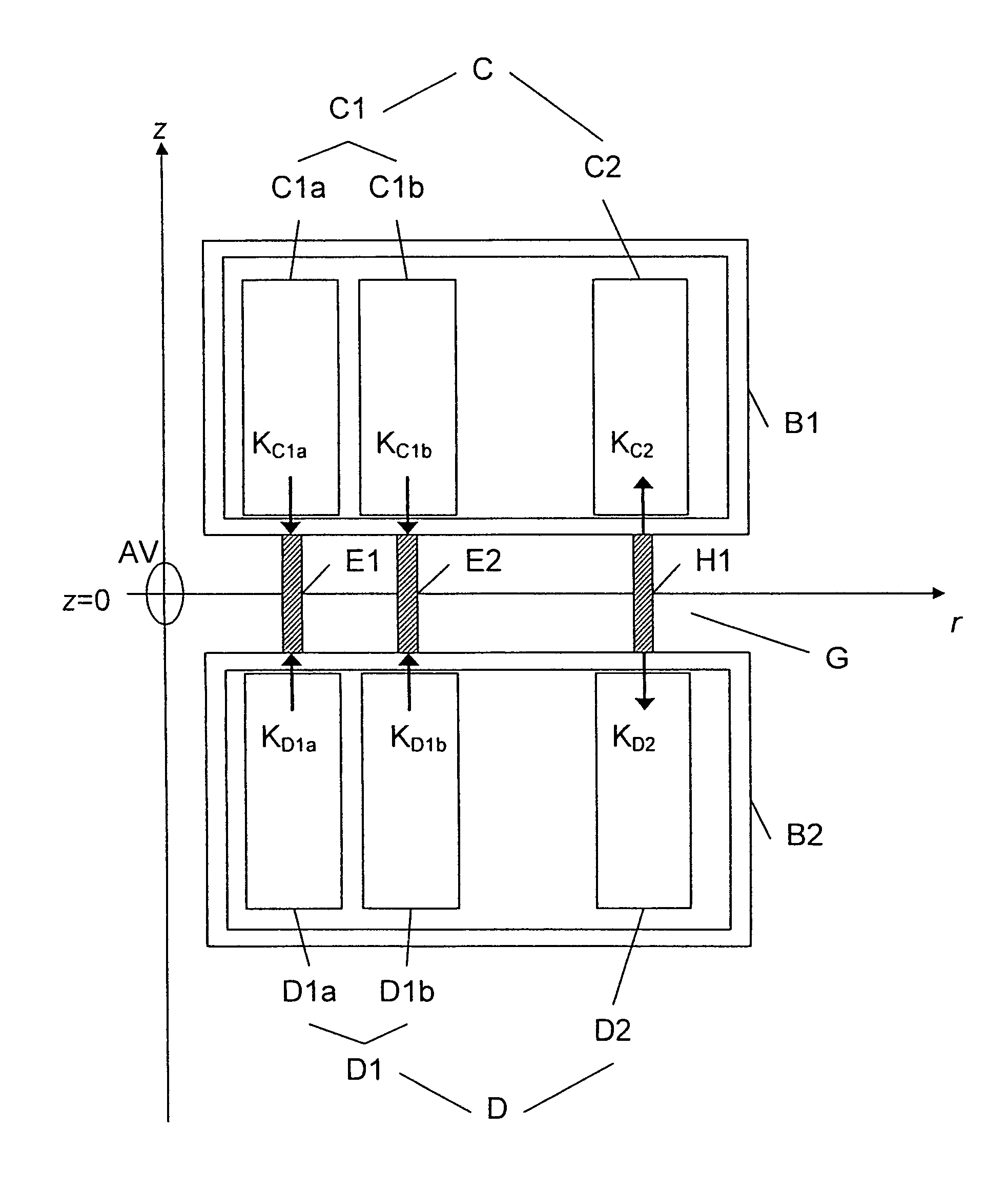
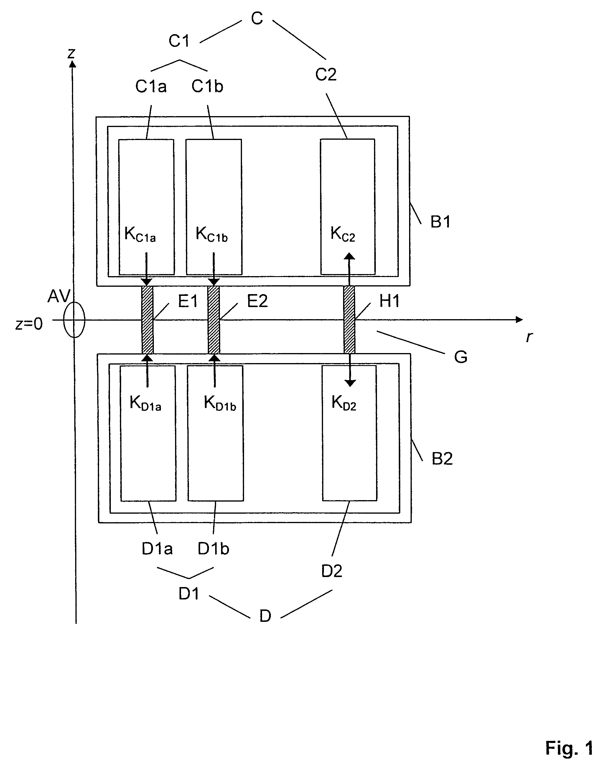
[0047]FIG. 8 shows a magnet arrangement according to the prior art that is arranged around a working volume AV and includes a magnet coil system M with two coil systems C, D for producing a magnetic field in the direction of a z axis. The two coil systems C, D are positioned in containers B1, B2 axially mechanically separated by a split G. Each coil system C, D includes a first coil section system C1, D1 and a second coil section system C2, D2. The first coil section system C1, D1 exhibit the same polarization and are exposed to magnetic forces acting toward the split G in the axial direction KC1, KD1. Each second coil section system C2, D2 is mounted radially outside the corresponding first coil section system C1, D1 and exhibits opposite polarization to the first coil section system C1, D1. The second coil section systems C2, D2 are used, for example, as compensation coils for the stray field of the magnet arrangement. In this arrangement, the second coil section systems C2, D2 ar...


PUM

PropertyMeasurementUnit
distanceaaaaaaaaaa
aperture angleaaaaaaaaaa
vertical magnetic fieldaaaaaaaaaa

Abstract

A magnet arrangement with a magnet coil system (M) with two coil systems (C, D) that are each arranged in a container (B1, B2) positioned around the z axis and that are axially mechanically separated by a split (G), wherein each coil system (C, D) comprises a first (C1, D1) and a second coil section system (C2, D2), wherein the first coil section systems (C1, D1) are exposed to attractive magnetic forces showing toward the split (G) (KC1, KD1) and the second coil section systems (C2, D2), to repulsive magnetic forces showing away from the split (G) (KC2, KD2), and containing in the split (G) at least one mechanical structure that withstands compressive loads (E1, E2) and that supports a part of the attractive magnetic forces (KC1, KD1), is characterized in that, in the split (G) within the dimensions of the containers (B1, B2), a mechanical structure (H1) is provided that mechanically withstands tensile loads in the z direction, supports a part of the repulsive magnetic forces in the axial direction (KC2, KD2), is connected to the containers (B1, B2) and holds them together. With the inventive magnet arrangement, the magnetic forces can be better controlled. At the same time, a low-cost, space and weight saving assembly can be implemented.

Description

[0001]This application claims Paris Convention priority of DE 10 2006 040 687.7 filed Aug. 30, 2006 the complete disclosure of which is hereby incorporated by reference.BACKGROUND OF THE INVENTION[0002]The invention relates to a magnet arrangement with a magnet coil system for generating a magnetic field in the direction of a z axis in a working volume arranged on the z axis around z=0 with two coil systems that are each arranged in a container positioned around the z axis, wherein the containers are mechanically axially separated from each other by a split, wherein the coil systems each include one first coil section system and at least one of the coil systems contains a second coil section system, wherein each coil section system comprises at least one coil body and at least one winding package, wherein the first coil section systems are exposed to magnetic forces acting in the axial direction toward the split, and wherein the second coil section systems are exposed to magnetic fo...

Claims


Application Information

Patent Timeline
Patent Type & Authority Patents(United States)
IPC IPC(8): H01F1/00G01V3/00H01F3/00H01F5/00H01F6/00H01F7/00
CPCG01R33/288G01R33/3802G01R33/3806G01R33/3815H01F27/306H01F6/06H01F7/202Y10S505/879
Inventor GILARDI, RAFFAELESCHNEIDER, STEFANSCHAUWECKER, ROBERTBOVIER, PIERRE-ALAIN
Owner BRUKER SWITZERLAND AG
Why Eureka
Try Eureka