Hydrant roof mount

a technology for mounting brackets and roofs, applied in mechanical equipment, drawing-off water installations, transportation and packaging, etc., can solve the problems of lack of structural support, prone to leakage, and insufficient support of structures, etc., to facilitate interconnection, facilitate installation, and light and easy to install

Active Publication Date: 2010-06-08
WCM IND INC
View PDF223 Cites 41 Cited by
  • Summary
  • Abstract
  • Description
  • Claims
  • Application Information

AI Technical Summary

Benefits of technology

[0006]A boot is also employed by embodiments of the present invention that helps ensure that fluids, for example, are prevented from entering the building. Embodiments of the present invention employ a boot constructed of material suitable to seal the structure when in use and to provide weather resistance, e.g. ethylene propylene diene monomer (EPDM) rubber with UV protection. The hydrant support may also be fitted with flashing material to mask the hydrant support.
[0007]It is also envisioned that at least one shim may be included to facilitate interconnection between the hydrant support and the roof. Preferably, a two degree shim is employed that is placed under the hydrant support to help ensure that the hydrant support is generally oriented vertically. One skilled in the art, however, will appreciate that the flange that is associated with the hydrant support may be constructed of varying thicknesses to compensate for roof pitch.
[0008]It is another aspect of the present invention to provide a system for supporting a hydrant that is easy to install. More specifically, embodiments of the present invention allow for the interconnection of a hydrant to a roof via a hydrant support wherein the hydrant support and associated boot are separable and easily interconnect to the standpipe. In addition, it is contemplated that a flange be used in conjunction with the hydrant support that is located under the roof that is used to sandwich the roof between the flange of the hydrant support and the flange located beneath the roof. This under deck flange may be constructed of a single piece of material with a plurality of holes incorporated therein, thereby making it light and easy to install.
[0009]It is yet another aspect of the present invention to provide a tight seal between the standpipe and the hydrant support. When interfacing the standpipe to the hydrant support, a series of seals may be employed wherein the tightening of at least one bolt increases the compression on an intermediate seal, thereby squeezing it tightly between the standpipe and the inner diameter of the hydrant support. As alluded to above, the sealing system may be enhanced by the use of a boot that covers the seals and that interfaces with the standpipe and the outer diameter of the hydrant support.

Problems solved by technology

Often hydrant and faucets are used on roofs but suffer from leaking and possess little structural support to accommodate the movement of a hose, for example.
For example, the penthouse structure may not offer sufficient support, the attachment scheme may be prone to leaks, freeze protection may be insufficient, and / or the attachment location may not be in close proximity to the required areas of use.
In addition, the prior art systems are often heavy and difficult to interconnect and they also provide unacceptable leak paths into the structure.

Method used


Image

  • Hydrant roof mount
  • Hydrant roof mount
  • Hydrant roof mount

Examples


Embodiment Construction

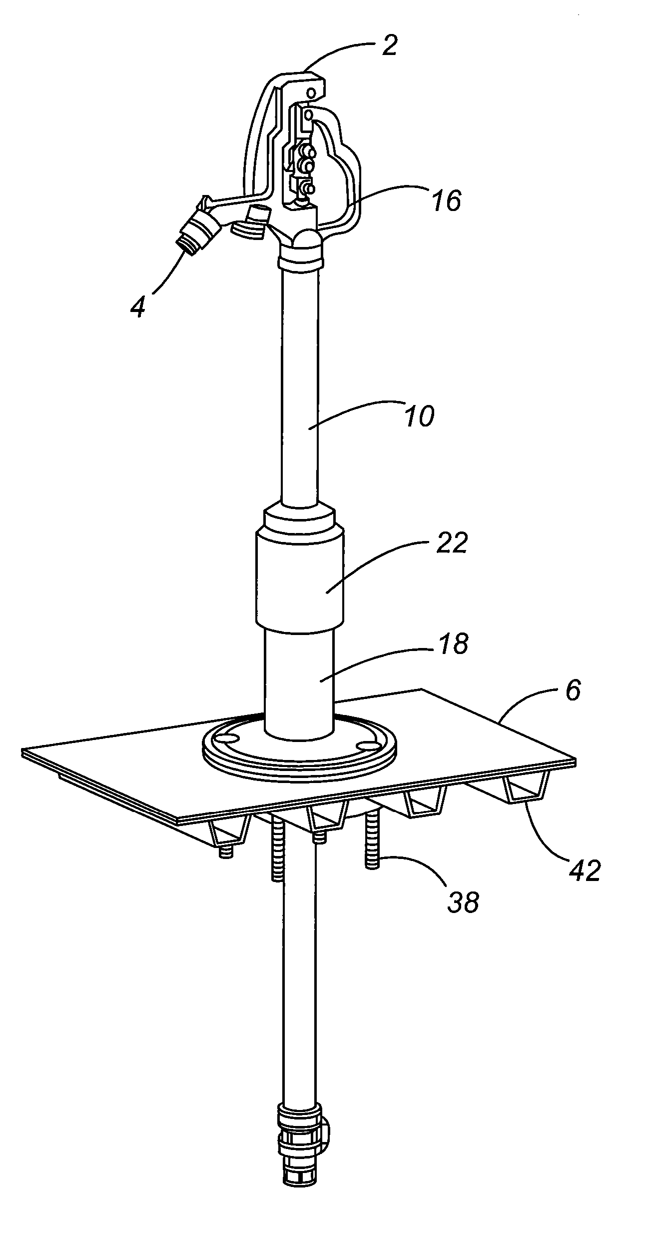
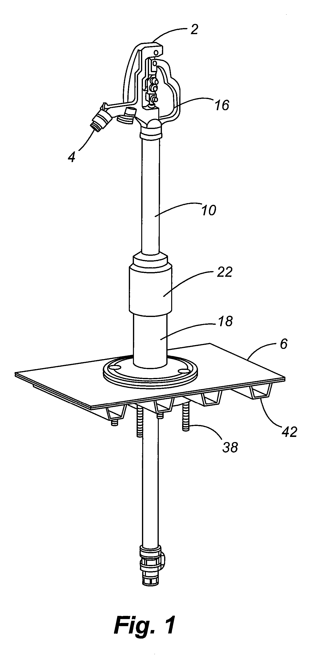
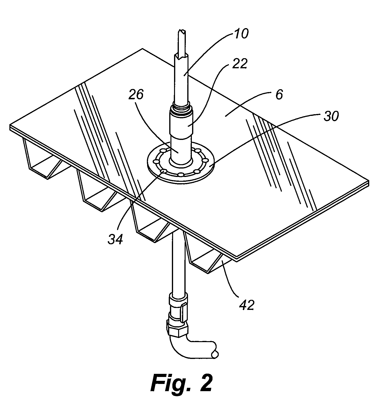
[0027]Referring now to FIGS. 1-12, a mounting system for securing a hydrant 2 to a roof deck 6 is provided. More specifically, embodiments of the present invention are used with a common hydrant 2 having a standpipe 10 that leads to a water supply 14. In the illustrated embodiment, the standpipe 10 is eventually interconnected to a water supply 14 that selectively is opened via a handle 16 of the hydrant 2. A hydrant support 18 provides rigidity to the standpipe 10. In order to ensure that substantially no fluid infiltrates into the inside of the building, a seal assembly 84, which includes an upper well seal 86, an intermediate seal 94, and a bottom seal 98, is employed that interfaces with the standpipe 10 and the hydrant support 18. A boot 22 may also be included to further provide leak resistance.

[0028]Referring now to FIGS. 1-6, the hydrant support of one embodiment of the present invention is shown that includes a tube 26 and a flange 30. Although shown herein, the tube 26 and...


PUM


Abstract

A system for securing a hydrant to a roof of a building is provided that includes a hydrant support that rigidly interconnects to the roof deck. In addition, a method of sealingly interconnecting a standpipe of the hydrant to the hydrant support is provided wherein a plurality of seals are employed. In order to enhance the seal provided between the standpipe and a hydrant support, a boot may be used that covers the interface between the standpipe and the hydrant support.

Description

[0001]This application claims the benefit of U.S. Provisional Patent Application Ser. No. 60 / 821,892, filed Aug. 9, 2006, the entire disclosure of which is incorporated by reference herein. This application is also a Continuation-In-Part of U.S. Design patent application Ser. No. 29 / 248,316, filed Aug. 9, 2006, now U.S. Pat. No. D,574,065, which is incorporated by reference in its entirety herein. This application is also a Continuation-In-Part of U.S. patent application Ser. No. 11 / 554,232, filed Oct. 30, 2006, now U.S. Pat. No. 7,472,718, which claims the benefit of U.S. Provisional Patent Application Ser. No. 60 / 596,962, filed Nov. 1, 2005, both disclosures of which being incorporated by reference in their entirety herein.FIELD OF THE INVENTION[0002]Embodiments of the present invention generally relate to a system for interconnecting a hydrant to the roof of a building or other structure.BACKGROUND OF THE INVENTION[0003]There is a growing need for a convenient and robust water so...

Claims


Application Information

Patent Timeline
Patent Type & Authority Patents(United States)
IPC IPC(8): E03B9/02
CPCE04D13/1407E03B9/04Y10T137/698Y10T137/0486Y10T137/5462
Inventor BALL, WILLIAM T.
Owner WCM IND INC
Why Eureka
Try Eureka