Panel quilting machine

a panel quilting machine and quilting machine technology, applied in the field of quilting of fabric materials, can solve the problems of reducing the amount of stretch, limiting the operation of the quilter, and reducing the amount of tension applied, so as to reduce the amount of stretch and reduce the tension

Active Publication Date: 2010-06-15
ATLANTA ATTACHMENT
View PDF47 Cites 17 Cited by
  • Summary
  • Abstract
  • Description
  • Claims
  • Application Information

AI Technical Summary

Benefits of technology

[0009]The quilter unit further includes a presser foot that extends transversely across the width of the quilting machine is driven in a vertically reciprocating manner off of the main drive shaft of the quilter unit. Both the presser foot and needle bar are driven off the main drive shaft by separate, adjustable eccentric drive linkages, which enables the presser foot and needle bar to be driven independently of each other. The presser foot and needle bar thus can engage the fabric material plies at different or varying intervals during a sewing operation to ensure that the needles are able to fully penetrate the multiple plies of the fabric material and that the loops of thread formed thereby will not be pulled loose as the needles are withdrawn from the fabric material. The threads are fed to the needles from a series of thread guides through one or more rows of thread breakage detectors. Multiple rows of thread breakage detectors can be provided as needed for enabling different threading sequences to be utilized for quilting multiple patterns in the fabric material. The quilter unit further can be programmed to quilt a variety of different patterns via movement of the fabric material in lateral and longitudinal directions within the sewing zone of the quilter unit.
[0012]Still further, the longitudinally oriented slitting blades can be adjustably and removeably mounted along their drive shaft via locking collars and locking hubs that can be remotely engaged via a tool so as to unlock and enable lateral movement of the slitting blades along their drive shaft to a desired position or to create a desired spacing between adjacent slitting blades, after which the blades are automatically locked in place. The slitting blades additionally can be formed as sectioned blades, typically formed in two halves or sections that can be brought into mating alignment and locked together by the engagement of clamp sections that engage the blade sections on opposite sides thereof. Such split blades enable quick and easy replacement of damaged slitting blades without having to remove the entire drive shaft and all the blades therealong.

Problems solved by technology

The operation of the quilting machines is, however, typically limited by factors such as the thicknesses of the materials being quilted, the patterns being formed, as well as by the mechanical linkage typically utilized between the presser foot and needle bar drive shaft for reciprocating the presser foot and needle bar drive shafts in a directly timed relationship.
The operation of the quilter also can be limited by the speed at which a panel cutter connected to the quilting machine can be operated.
Changing or adjusting the position of the slitting blades of the panel cutter can, however, be a substantially time consuming operation, as the blades typically must be uncoupled from the blade drive shaft along which they are mounted and thereafter shifted with respect to each other to cut the quilted material at the desired spacings, after which the slitting blades must be re-secured to their drive shaft.
This adjustment procedure can be a time consuming and somewhat dangerous operation as it typically requires the operator to physically handle and move the slitting blades, which can cut or otherwise injure the operator.
These adjustments typically can require the use of complex electronic position controls or manual adjustment of the individual cams between the presser foot drive shaft and needle bar rocker shaft.
Other problems that can limit the operation of such quilting and panel cutting systems include bunching or jamming of the materials being quilted under the presser foot, or one or more layers of the material running out.

Method used


Image

  • Panel quilting machine
  • Panel quilting machine
  • Panel quilting machine

Examples


Embodiment Construction

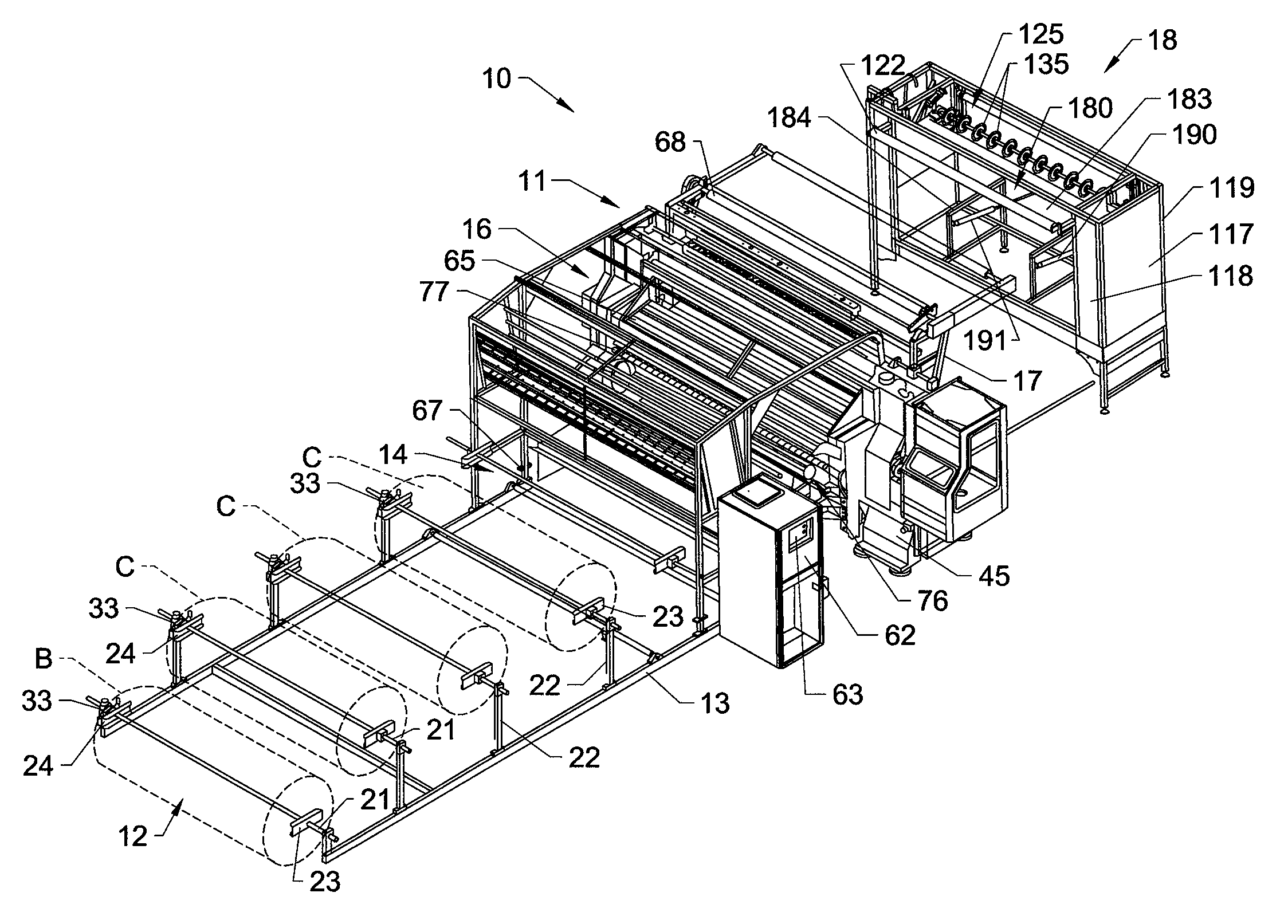
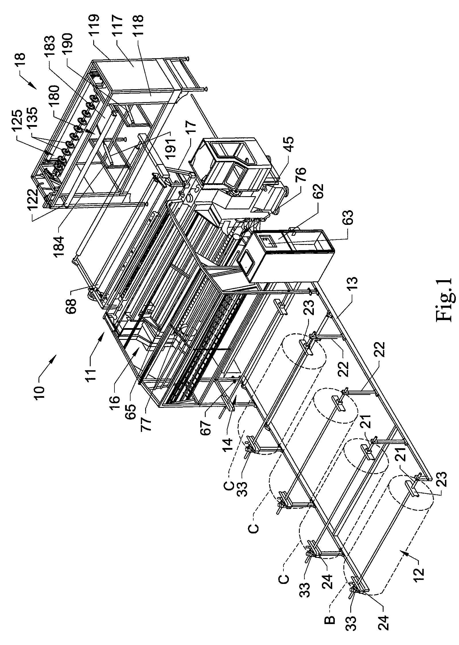
[0024]The present invention generally is directed to an improved system 10 and method of quilting fabric textile materials, typically for use as mattress panels, borders, gussets and other components for mattresses and foundation sets. The quilting system 10 of the present invention and various inventive features thereof, are shown in FIGS. 1-5B of the drawings.

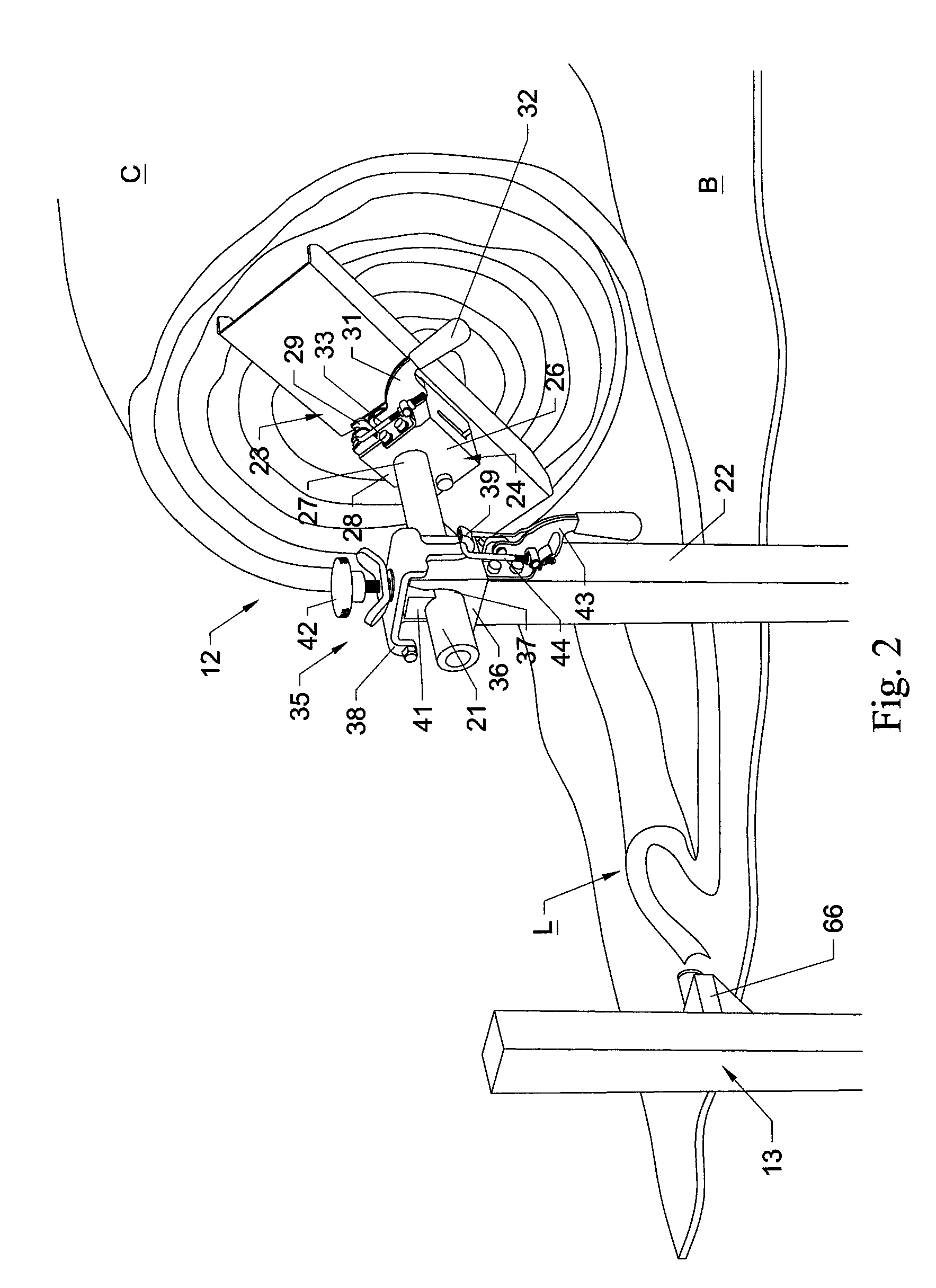
[0025]As generally indicated in FIG. 1, the quilting system 10 of the present invention will including a quilting machine or quilter unit 11 that receives a series of plies or layers of woven and non-woven fabric or other textile backing materials B, which can include one or more upper and lower plies of an outer facing fabric material, with a foam fill or similar cushioning material layer C being received therebetween. The backing and cushioning materials will be fed from a series of supply rolls 12, typically mounted on a rack 13 positioned upstream from an input or first side 14 of the quilting machine, with the backing an...


PUM


Abstract

A system for quilting fabric materials includes a quilter unit having a reciprocating needle bar with a series of needles spaced therealong and carrying a series of threads for forming quilted patterns in fabric materials passing below the needles. The quilted fabric materials then can be collected on a supply roll or fed to a panel cutter downstream from the quilter unit. The panel cutter can include a panel cutting blade for cutting the quilted material in different panel lengths or sizes, as well as a series of slitting blades that can be moved into engagement with the quilted material for forming strips of the quilted material in desired widths.

Description

CROSS-REFERENCE TO RELATED APPLICATIONS[0001]This application claims the benefit of U.S. Provisional Application Ser. No. 60 / 775,657, filed Feb. 22, 2006, entitled “Panel Quilting Machine,” the entire contents of which is hereby incorporated by reference as if presented herein in its entirety.FIELD OF THE INVENTION[0002]The present invention generally relates to the quilting of fabric materials, and in particular to a system and method of quilting fabric panels that can be slit or cut to form panels, borders, and other components for mattresses and other bedding items.BACKGROUND OF THE INVENTION[0003]Many mattresses today include borders, top and bottom panels, and other components that are formed with quilted patterns along their surfaces. The quilting of such patterns generally is designed to provide a decorative, aesthetically pleasing appearance to the panels, borders, and other components, as well as to attach together the different layers or plies of materials for the panels. ...

Claims


Application Information

Patent Timeline
Patent Type & Authority Patents(United States)
IPC IPC(8): D05B11/00D05B37/00
CPCD05B37/04D05B11/00
Inventor PRICE, ELVIN C.DASHER, PRESTON B.BAKER, MICHAEL G.MURPHY, DANNY V.PRICE, GEORGE A.PHILLIPS, JOHN P.KANE, JEFFREY S.
Owner ATLANTA ATTACHMENT
Why Eureka
Try Eureka