
Digital camera with dual optical systems

a digital camera and optical system technology, applied in the field of digital cameras with dual optical systems, can solve the problems of consuming a certain period of time, and reducing the service life of digital cameras

Active Publication Date: 2010-06-15
APPLE INC
View PDF5 Cites 113 Cited by
  • Summary
  • Abstract
  • Description
  • Claims
  • Application Information

AI Technical Summary

Benefits of technology

The present invention provides an image-capturing apparatus with multiple image-capturing systems that can change their angle of view. The apparatus includes a selecting system for selecting one of the image-capturing systems and rendering it operative. The selected system can change its angle of view based on external input. The other image-capturing systems can switch between two different angle of views based on the angle of view of the selected system. This allows for quick switching of the angle of view. The technical effect of this invention is to provide a versatile image-capturing system that can capture images from different angles and ranges.

Problems solved by technology

However, when the digital camera is provided with a lens of wide zoom range without sacrificing the quality of a captured image, the digital camera becomes bulky.
However, a compact digital camera does not enable replacement of lenses.
However, in the configuration where the first and second image-capturing optical systems are sequentially actuated from the wide position to the telephotography position, consumption of a certain period of time is required before the system arrives at the telephotography position; namely, the second image-capturing optical system arrives at the telephotography position.
This may result in a case where the chance to activate a shutter is lost.
Such a user's demand cannot be met by the above driving methods.

Method used


Image

  • Digital camera with dual optical systems
  • Digital camera with dual optical systems
  • Digital camera with dual optical systems

Examples


Embodiment Construction

[0035]An embodiment of the present invention will be described hereunder by reference to the drawings.

Basic Configuration

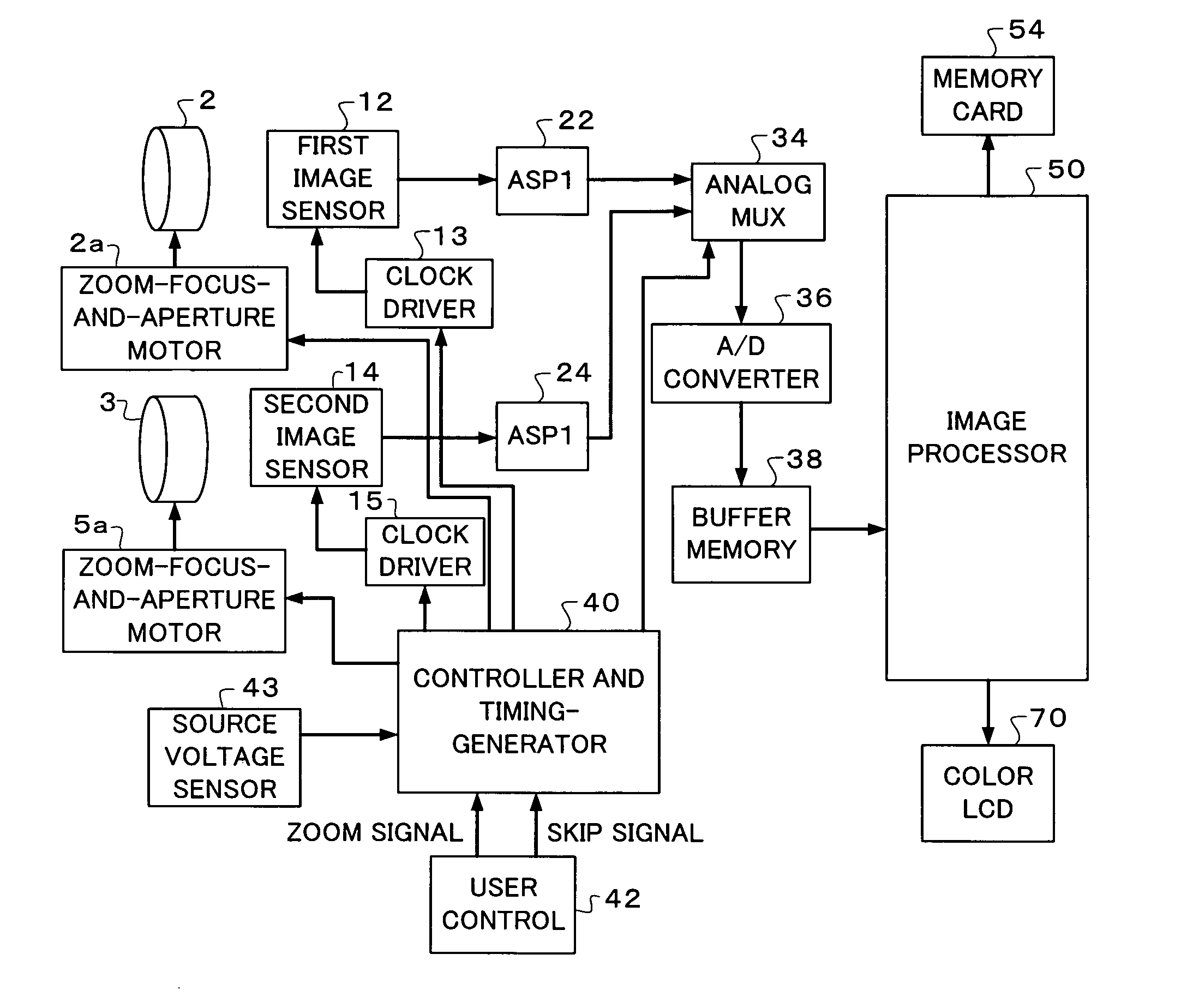
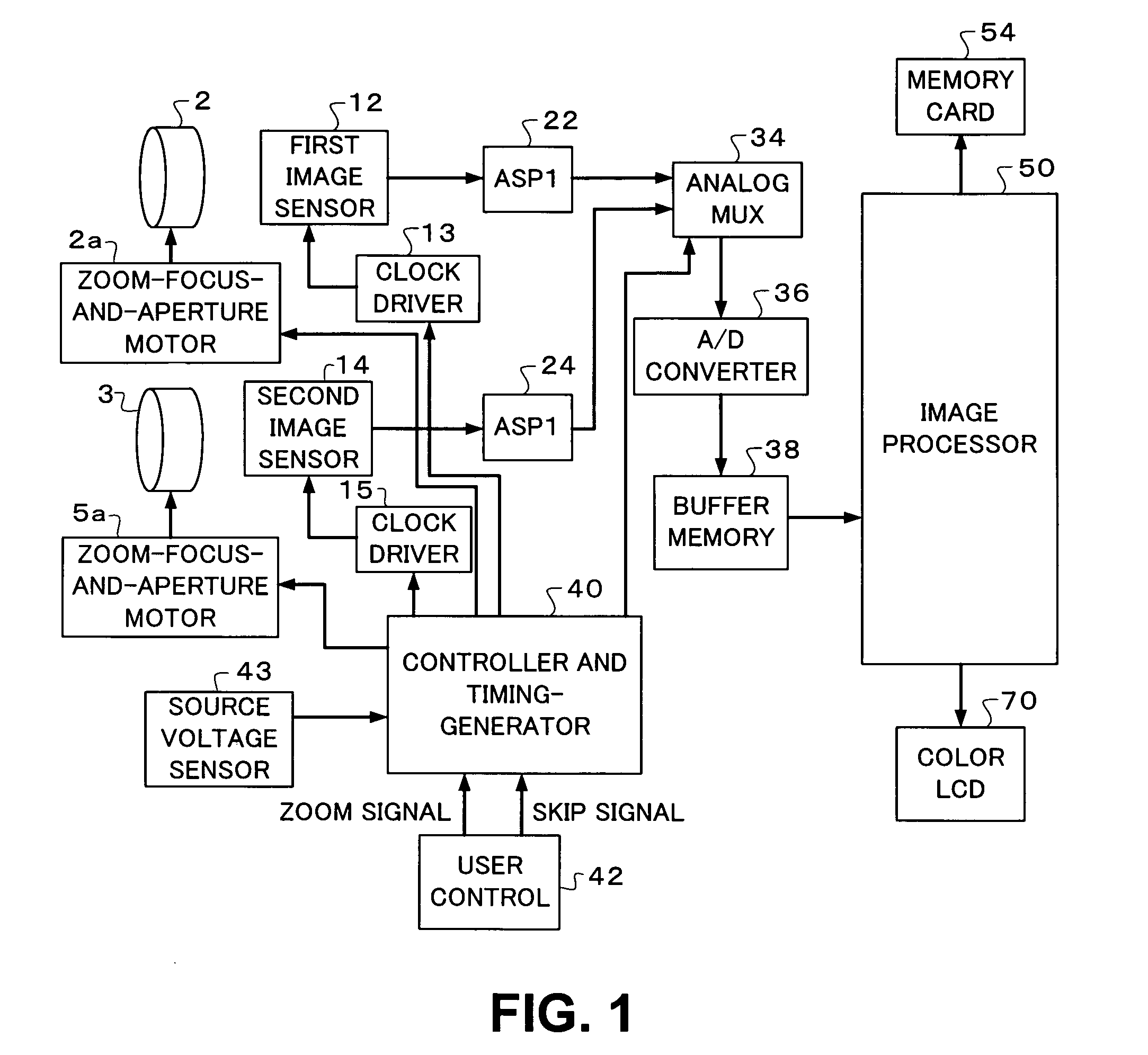
[0036]FIG. 1 shows a block diagram of the basic configuration of a digital camera according to a present embodiment. A digital camera is a portable, battery-operated camera. The digital camera generates a still digital image stored in a removable memory card 54. In addition to generating a still image, the digital camera may generate a digital motion picture alternatively or concurrently with the still image. The digital motion picture is similarly stored in the memory card 54.

[0037]The digital camera includes an image capture assembly. The image capture assembly comprises a first zoom lens 2 for forming an image of a scene on a first image sensor 12 and a second zoom lens 3 for forming an image of the same scene on a second image sensor 14. The image capture assembly provides a first image output from the first image sensor 12 and a second image output from the s...


PUM


Abstract

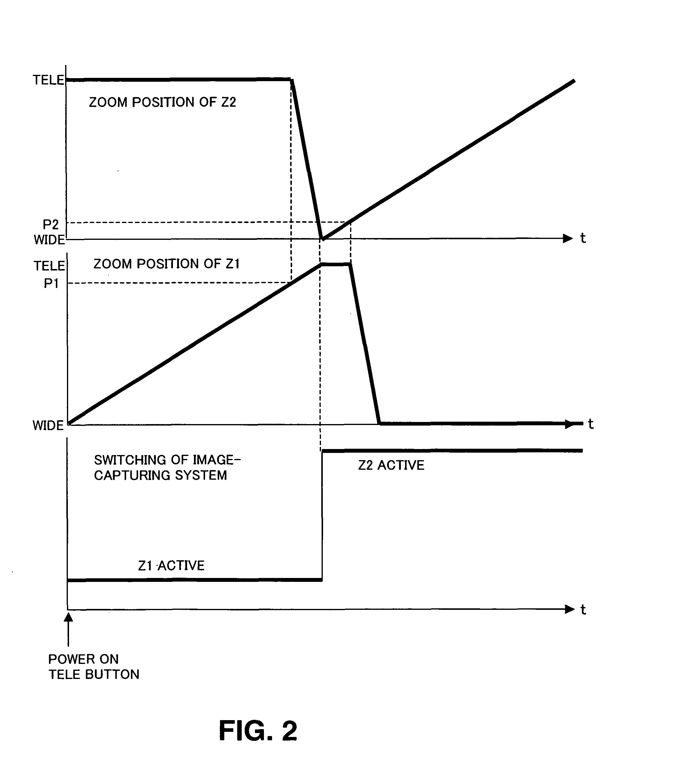
A digital camera has a first optical system having a wide zoom lens and a second optical system for a telephotography zoom lens. In an initial state where power is active, a controller and timing-generator controls the wide zoom lens so as to be situated at a wide position and the telephotography zoom lens so as to be situated at a telephotograph position. When zoom-in is effected, the wide zoom lens is actuated, and the telephotography zoom lens is maintained at the telephotograph position. When a zoom position of the wide zoom lens has reached a threshold zoom position set to a wider angle of view than that achieved at the telephotograph position, the telephotography zoom lens starts being actuated toward the wide position. When the zoom lens has reached the telephotograph position, an image signal is switched from the wide zoom lens to the telephotography zoom lens, and the selected image signal is output.

Description

CROSS REFERENCE TO RELATED APPLICATIONS[0001]This application claims priority to Japanese Patent Application No. 2006-028364 filed on Feb. 6, 2006, which is incorporated herein by reference in its entirety.BACKGROUND OF THE INVENTION[0002]1. Technical Field[0003]The present invention relates to an image-capturing apparatus such as a digital camera or the like, and more particularly to an image-capturing apparatus having a plurality of optical systems for capturing an image of a scene.[0004]2. Related Art[0005]Many current digital cameras have a zoom lens and a single image sensor and capture a still image and a motion picture. The thus-captured image is digitally processed to thus create a digital image file, and the thus-created film is stored in memory in the digital camera. The digital image file is then transferred to a computer to be displayed thereon or to a printer to be printed thereby.[0006]Desired specifications of a digital camera include compactness and a wide range of a...

Claims


Application Information

Patent Timeline
Patent Type & Authority Patents(United States)
IPC IPC(8): H04N5/262G02B15/14G03B17/00
CPCH04N5/262H04N5/232H04N23/60
Inventor TOYOFUKU, TOSHIYUKI
Owner APPLE INC
Learn More