Trench isolated capacitive micromachined ultrasonic transducer arrays with a supporting frame

a capacitive micromachined ultrasonic transducer and supporting frame technology, applied in the field of ultrasonic transducers, can solve the problems of difficult wafer-to-wafer fusion bonding, limited through-wafer via approach, and difficult separation of carrier wafer and membran

Active Publication Date: 2010-06-22
THE BOARD OF TRUSTEES OF THE LELAND STANFORD JUNIOR UNIV
View PDF4 Cites 40 Cited by
  • Summary
  • Abstract
  • Description
  • Claims
  • Application Information

AI Technical Summary

Benefits of technology

[0006]A trench-isolated CMUT array with a supporting mesh frame for fully populated 1D and 2D arrays is provided. According to the current invention, the CMUT array is built on a silicon-on-insulator (SOI) wafer. Electrical interconnections to array elements are provided through the highly conductive silicon substrate. Neighboring array elements are separated from one another by trenches on both the device layer and the bulk silicon. A mechanically supporting frame is designed as a mesh structure between the silicon pillars providing electrical connections to the individual elements. The framed trench isolation is compatible with both wafer-bonded and surface-micromachined CMUTs. The invention eliminates the need for attaching the device wafer to a carrier wafer for the required mechanical support during the deep trench etching and flip-chip bonding steps, which presents difficulties during the release of the carrier wafer.

Problems solved by technology

In large, fully populated 1D and 2D transducer arrays, providing connection to each array element is a challenge.
It was found that after the deposition of the polysilicon, performing wafer-to-wafer fusion bonding is difficult.
Therefore, the through-wafer via approach is limited to only surface micromachining CMUT processes.
This particular requirement presents certain drawbacks in processing.
However, it is difficult to separate the carrier wafer and the membrane after the flip-chip bonding.
The adhesive material may also swell in the solvent, creating stress that can break the CMUT membranes.

Method used


Image

  • Trench isolated capacitive micromachined ultrasonic transducer arrays with a supporting frame
  • Trench isolated capacitive micromachined ultrasonic transducer arrays with a supporting frame
  • Trench isolated capacitive micromachined ultrasonic transducer arrays with a supporting frame

Examples


Embodiment Construction

[0024]Although the following detailed description contains many specifics for the purposes of illustration, anyone of ordinary skill in the art will readily appreciate that many variations and alterations to the following exemplary details are within the scope of the invention. Accordingly, the following preferred embodiment of the invention is set forth without any loss of generality to, and without imposing limitations upon, the claimed invention.

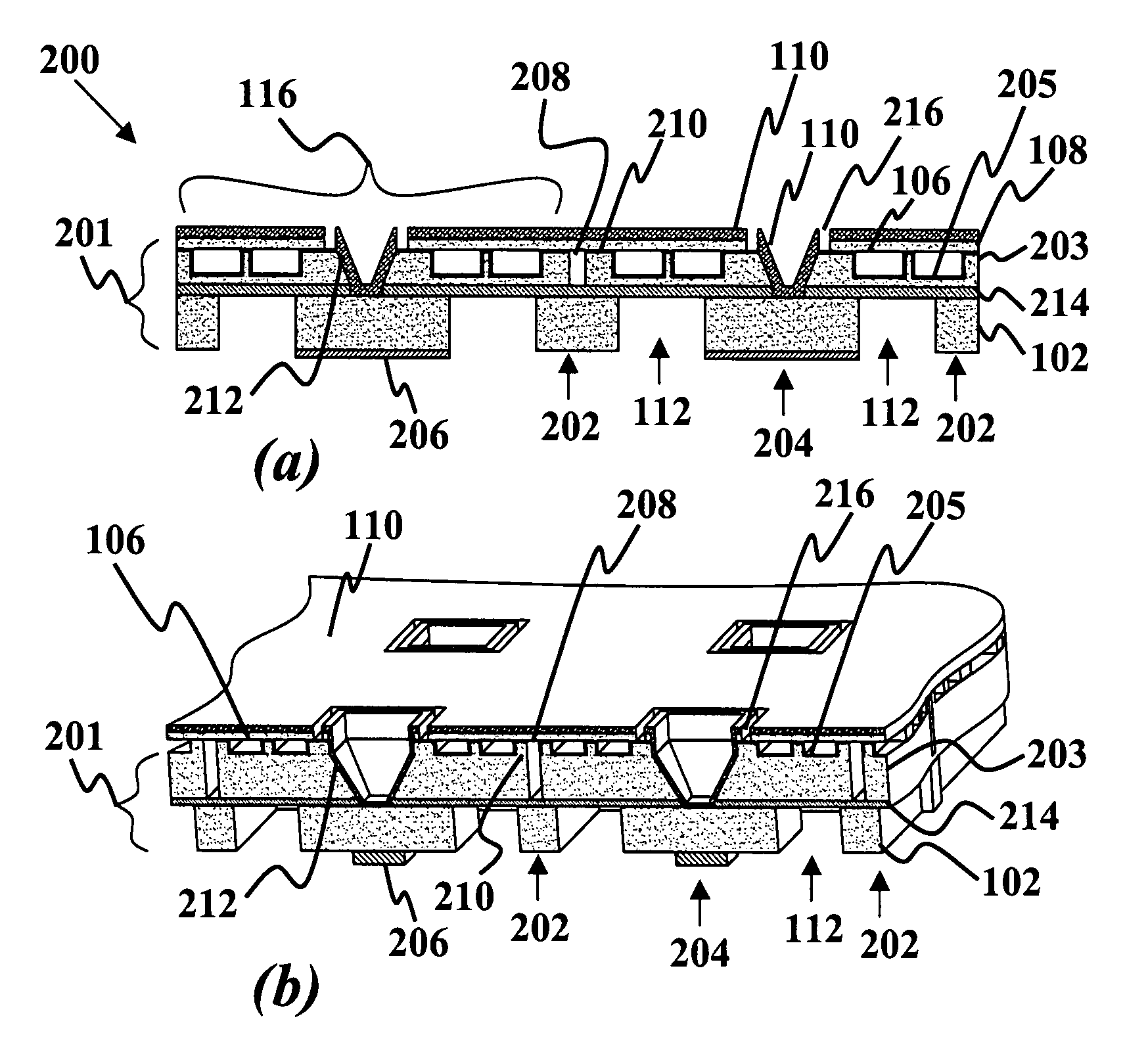
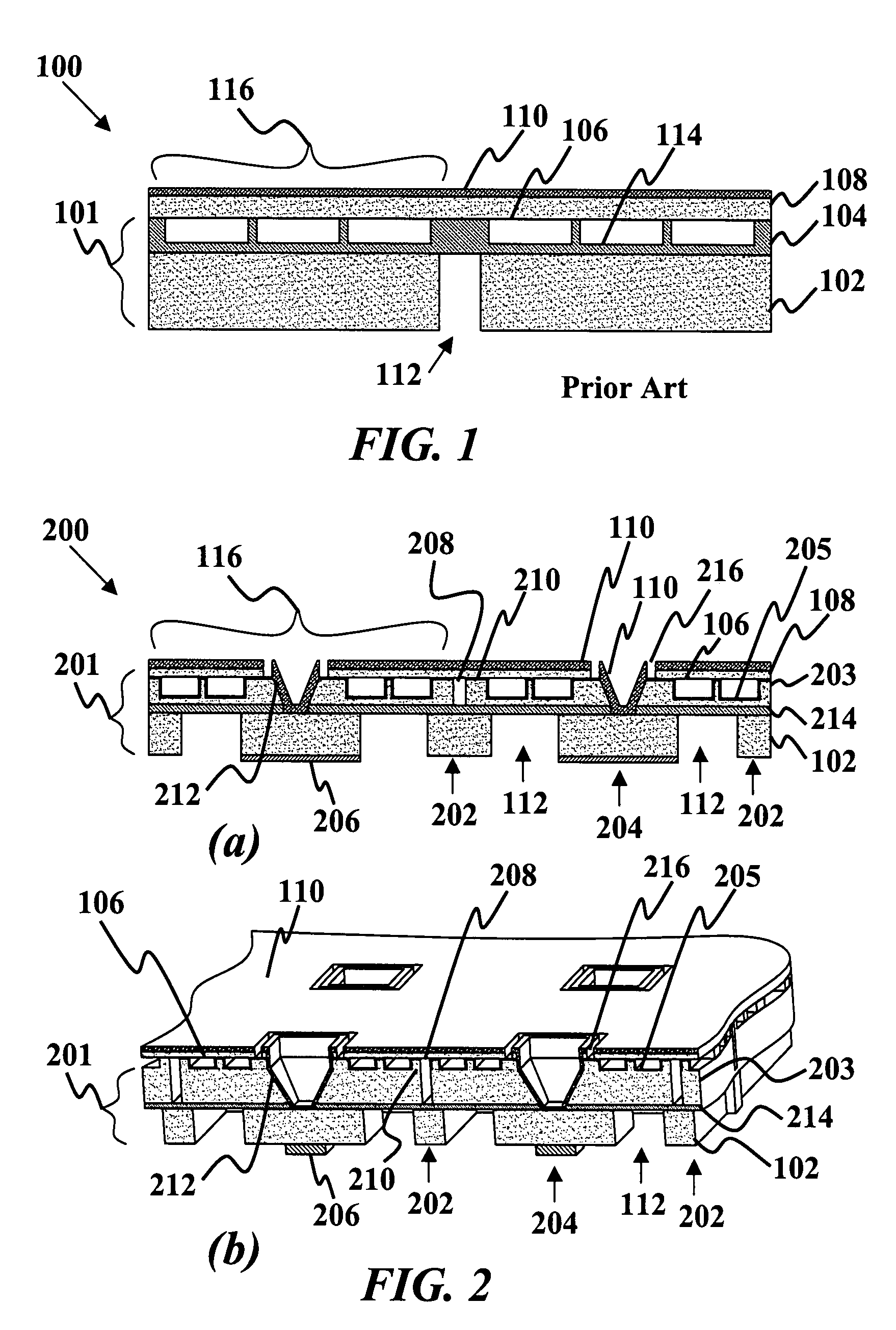
[0025]FIG. 1 shows a schematic cross-section planar view of a prior art trench isolated CMUT without supporting frame 100. Shown is a prime silicon wafer 101 having a silicon layer 102 of bulk silicon holding an oxide layer 104 having CMUT cell cavities 106 covered with a membrane / top metal layer 108 as a conductive front electrode, where the bulk silicon 102 is a back electrode. The conductive bulk silicon 102 has an isolation trench 112 for separating the array elements 116 for improved array performance.

[0026]Typically, a carrier wafer...


PUM


Abstract

A one or two-dimensional capacitive micro-machined ultrasonic transducer (CMUT) array with supporting frame is provided. The CMUT array has at least three array elements deposited on a conductive substrate. The invention also has at least one CMUT cell in the array element, a conductive top layer deposited to a top side of the element, and a conductive via disposed within the elements. The via is isolated from the conductive top layer and conducts with the substrate. There are at least two isolation trenches in the conductive substrate, and the trenches are disposed between adjacent vias to conductively isolating the vias. A substrate region between the trenches forms a mechanical support frame. At least one conductive electrode is deposited to a bottom surface of the conductive substrate, where the electrode conducts with the via. The support frame eliminates the need for a carrier wafer in the process steps.

Description

CROSS-REFERENCE TO RELATED APPLICATIONS[0001]This application is cross-referenced to and claims the benefit from U.S. Provisional Patent Application 60 / 832,317 filed Jul. 20, 2006, which is hereby incorporated by reference.STATEMENT REGARDING FEDERALLY SPONSORED RESEARCH OR DEVELOPMENT[0002]The present invention was supported in part by grant number CA099059 from the NIH. The U.S. Government has certain rights in the invention.FIELD OF THE INVENTION[0003]The invention relates generally to ultrasonic transducers. More particularly, the invention relates to one-dimensional and two-dimensional trench isolated capacitive micro-machined ultrasonic transducer (CMUT) arrays built on a silicon-on-insulator (SOI) wafer having a supporting mesh frame using either wafer-bonding or sacrificial release methods.BACKGROUND[0004]In large, fully populated 1D and 2D transducer arrays, providing connection to each array element is a challenge. In the case of 2D CMUT arrays, researchers have reported o...

Claims


Application Information

Patent Timeline
Patent Type & Authority Patents(United States)
IPC IPC(8): H01L29/93
CPCH01L27/1203B06B1/0292
Inventor KHURI-YAKUB, BUTRUS T.ZHUANG, XUEFENGERGUN, ARIF SANLI
Owner THE BOARD OF TRUSTEES OF THE LELAND STANFORD JUNIOR UNIV
Why Eureka
Try Eureka