Removable hat accessory

a hat and accessory technology, applied in the field of hat accessories, can solve the problems of compromising the security of the interference fit between the respective devices, failure of the device, and fracture of the bottom member, and achieve the effect of enlarge the space, stable and secure attachmen

Inactive Publication Date: 2010-06-29
NAMKUNG PROMOTIONS
View PDF32 Cites 10 Cited by
  • Summary
  • Abstract
  • Description
  • Claims
  • Application Information

AI Technical Summary

Benefits of technology

[0011]In one embodiment, the spring member can be used as an attaching device directly for removable attaching a display object to the button of the hat. Similarly, the spring member includes an upper spring portion, a lower spring portion, and a joint spring portion to connect the upper spring portion and the lower spring portion. The lower spring portion has one distal end in the form of two parallel leaves to extend underneath the button of the hat until the button is aligned under the space defined by the upper spring portion and the lower spring portion and one proximal end connected to the upper spring portion via the joint spring portion. Preferably, without the application of any external force, the space between the upper spring portion and the lower spring portion is substantially the same or slightly smaller than the height of the button. Therefore, to allow the lower spring portion to slide through the button from underneath, the joint spring portion is slightly bent or flexed to enlarge the space. When the button is received within space, the joint spring portion is released, and the restoration force exerted from upper and lower spring portions will press against the button within the space. Therefore, the spring member is prevented from sliding away from the button of the hat.
[0012]The display object to be attached to the hat includes a slot recessed from at a bottom surface thereof for receiving at least the upper spring portion of the spring member therein. Preferably, the display object can be split into two lateral mating parts each having a bottom surface configured to form half of the slot. Therefore, by aligning the half slots with two opposing sides of the upper spring portion and approaching the lateral portions towards each other, the upper spring portion is embedded within the display object. To provide a more stable and secure attachment between the display object and the spring member, the slot is configured to receive both the upper spring portion and the joint spring portion of the spring member. Interlocking means such as projecting posts and mating sleeves can be formed at the interior of the respect lateral portions, so as to ensure the integrity of the display object and to secure the attachment between the display object and the spring member.

Problems solved by technology

As such, interference between the button and the bottom coils of the spring secures the device to the hat.
Thus, interference between the bottom member and the button secures the device to the hat.
However, as both Knutson and Stazo require members that locally flex in order to achieve an interference fit, repeated attachment and removal of the device, that is, repeated flexure can eventually lead to failure of the devices.
Likewise, repeated attachment and detachment of the Stazo device can eventually fracture the portion of the bottom member.
In both cases, a secure interference fit between the respective devices is compromised.

Method used


Image

  • Removable hat accessory
  • Removable hat accessory
  • Removable hat accessory

Examples


Embodiment Construction

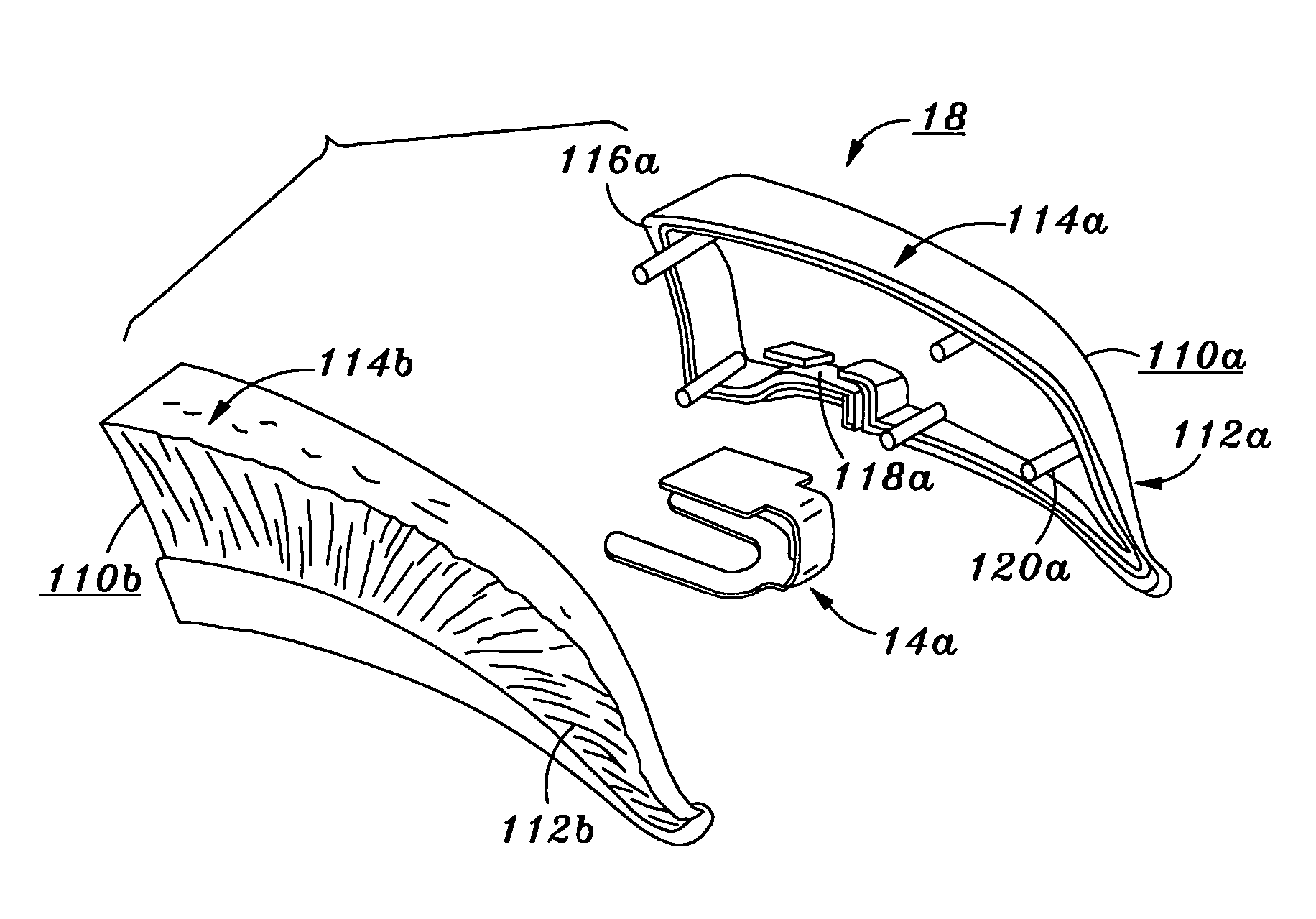
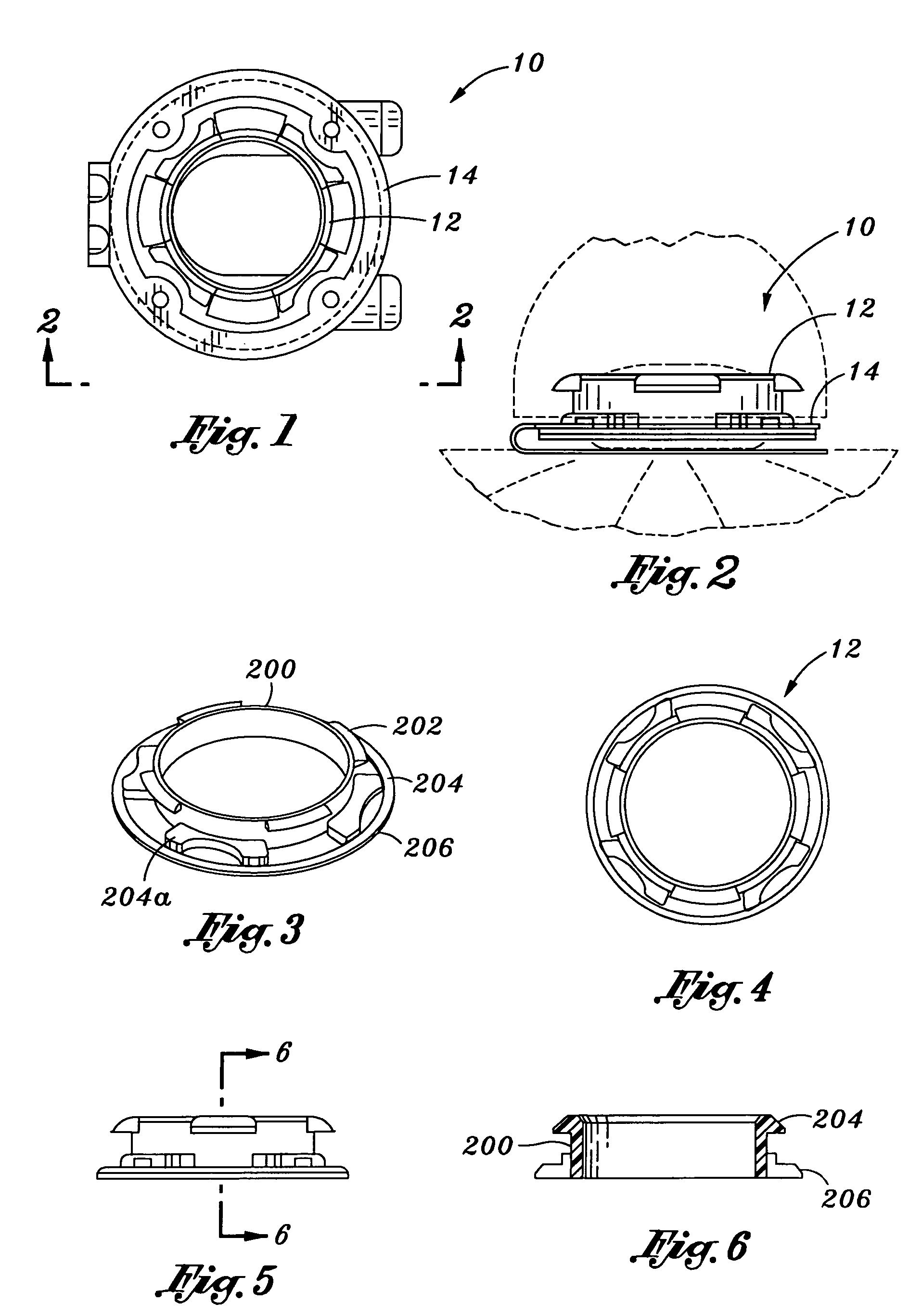
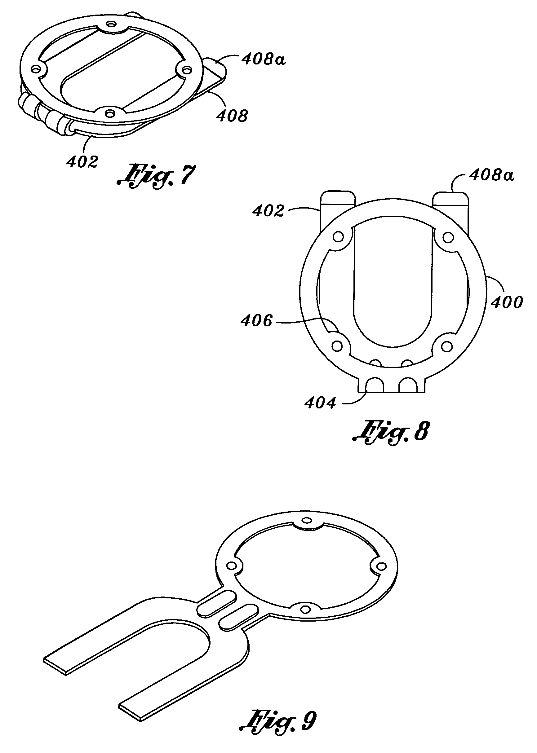
[0021]An attaching device for removably attaching a display object to a button of a hat or a cap is provided, and various views an exemplary attaching device and various parts thereof are illustrated in FIGS. 1 to 9. As shown in FIGS. 1 and 2, the attaching device 10 for removably attaching a display object (schematically indicated by phantom lines in FIG. 2) to a button of a hat includes a fastener 12 and a spring member 14. As shown in FIGS. 3-6, the fastener 12 is in the form of a plastic ring 200 with a predetermined height, a plurality of fins 202 projecting radially from a top rim of the plastic ring 200, and a plurality of tabs 204 extending from a bottom rim of the plastic ring 200. Preferably, the tabs 204 are formed under the spaces between adjacent fins 202; and therefore, the fins 202 and the tabs 204 alternatively and radially protrude from the top rim and the bottom rim of the plastic ring 200 along the outer perimeter of the plastic ring 200. In one embodiment, the ce...


PUM


Abstract

An attaching device for removably attaching various types of display objects to a hat. The attaching device has a fastener for engaging with the display object and a spring member for retaining the fastener therein and attaching to a button of the hat. The fastener is in the form of a plastic ring with a plurality of tabs projecting from a bottom rim thereof. The spring member has an upper spring portion, a lower spring portion and a joint spring portion connecting the upper and lower spring portions. The upper spring portion has an inner perimeter substantially the same as the maximum radial extent of the tabs, such that the plastic ring can be inserted therein. A plurality of protrusions is formed to extend inwardly from the inner perimeter of the upper spring portion. The protrusions are outline with a profile mating that of the tabs, such that the plastic ring can be secured interlocked with the spring member. The lower spring portion has an open end split into two parallel leaves, such that, by bending the joint spring to open the space between the upper and lower spring portions, the spring member can slide towards the button to receive the button within the space between the upper and lower spring portions.

Description

CROSS-REFERENCE TO RELATED APPLICATIONS[0001]This invention is a continuation-in-part of an earlier filed application Ser. No. 11 / 145,882, entitled “Removable Hat Accessory” filed Jun. 6, 2005, now U.S. Pat. No. 7,389,567 which is a continuation-in-part of an earlier filed application Ser. No. 10 / 645,368, entitled “Removable Hat Accessory” filed Aug. 21, 2003, now U.S. Pat. No. 7,350,274, the disclosures of which are expressly incorporated herein by reference.STATEMENT RE: FEDERALLY SPONSORED RESEARCH / DEVELOPMENT[0002]Not ApplicableBACKGROUND[0003]The invention relates in general to hat accessories, and more particularly, to an attaching device allowing various types of display or ornamental object to be removably attached to a button found on conventional hats / caps.[0004]In order to make the hats more visually appealing for various reasons such as displaying promotions and comedic effect, many hats, especially baseball-style caps, typically include a central button at their apex. T...

Claims


Application Information

Patent Timeline
Patent Type & Authority Patents(United States)
IPC IPC(8): A44B1/38A42B1/24A44B1/04A44B1/14
CPCA42B1/24A44B1/04A44B1/14Y10T24/1394Y10T24/13Y10T24/3672
Inventor ROGERS, JAMES R.
Owner NAMKUNG PROMOTIONS
Why Eureka
Try Eureka