
Anti-tilt apparatus and frame structure of tilting vehicle using the same

a technology of anti-tilt apparatus and frame structure, which is applied in the direction of cycle equipment, instruments, tractors, etc., can solve the problem of not automatically locking the vehicle, and achieve the effect of improving stability and anti-overturn ability

Inactive Publication Date: 2010-06-29
IND TECH RES INST
View PDF2 Cites 6 Cited by
  • Summary
  • Abstract
  • Description
  • Claims
  • Application Information

AI Technical Summary

Benefits of technology

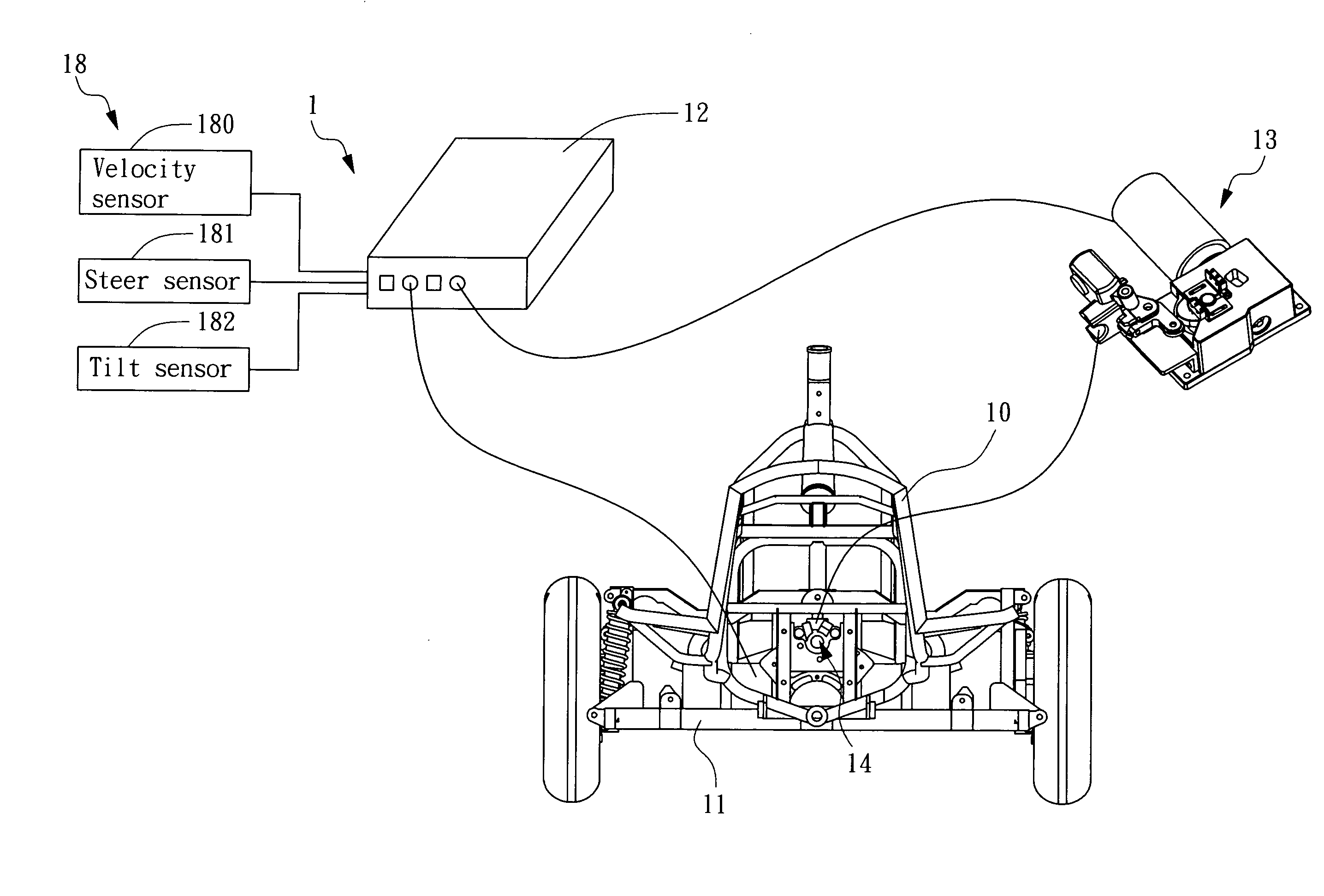
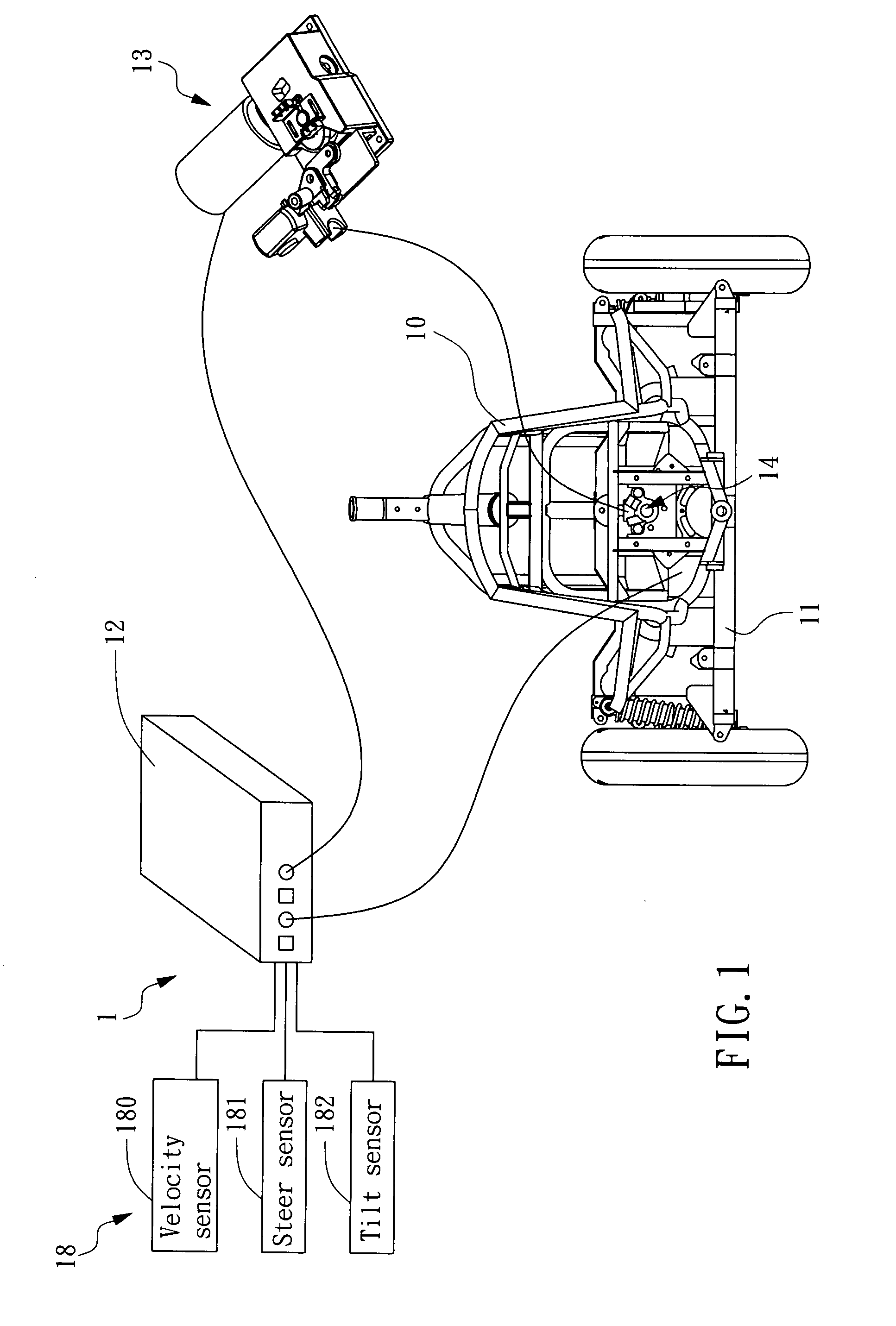
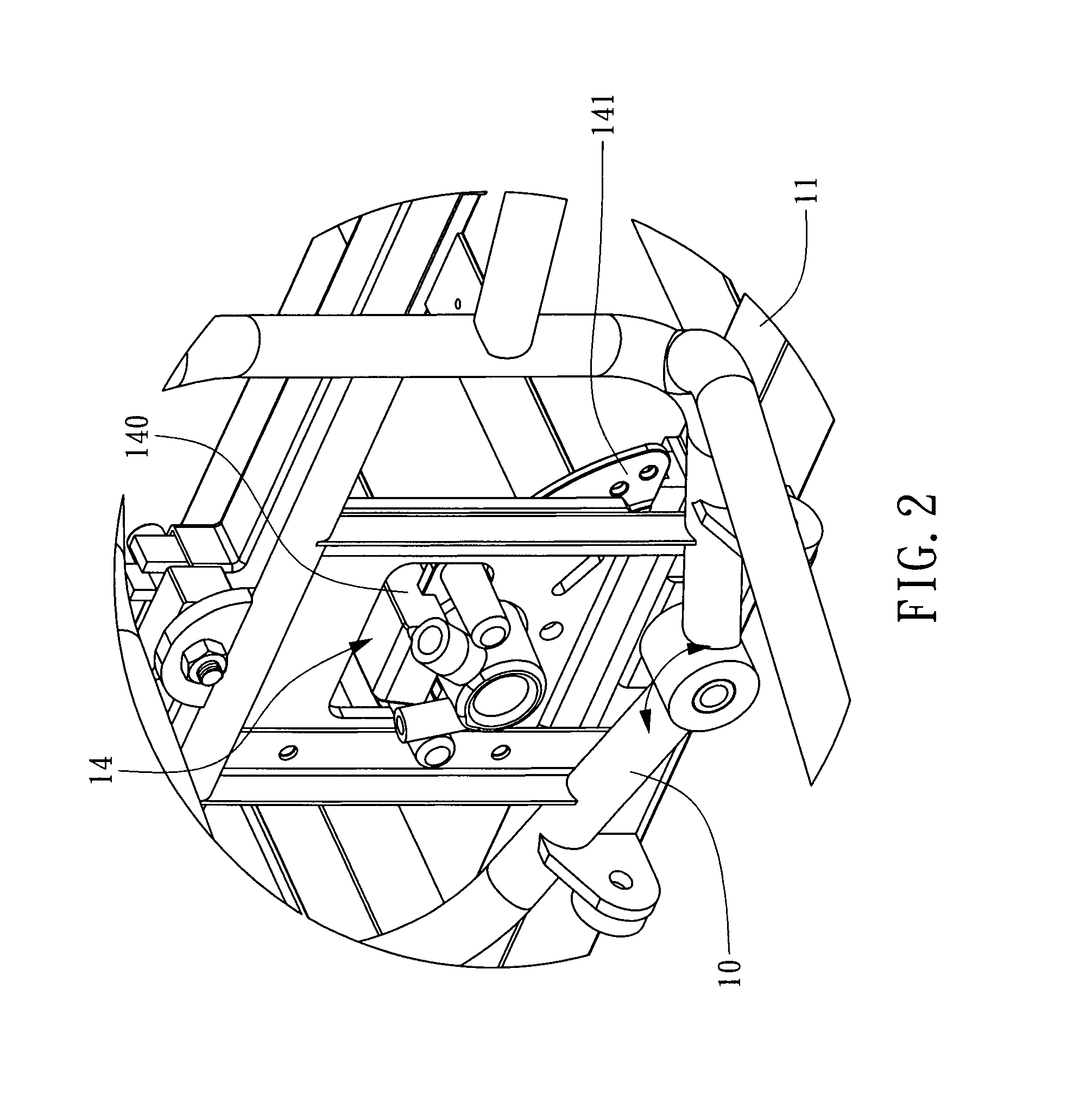
[0005]The object of the present invention is to provide an anti-tilt apparatus, capable of controlling a locking mechanism to lock or release a vehicle frame for tilting, and thereby, enabling a tilting vehicle using the frame to have its frame locked while cruising in low speed or stop, and to have it frame released for providing the vehicle with enhanced stability and anti-overturn ability while swerving in high speed.
[0006]Another object of the invention is to provide a vehicle frame for tilting vehicles integrating an anti-tilt apparatus and a structure for enabling independently suspended wheels to lean with the vehicle frame, capable of enabling the vehicle to maintain a certain comfort, and possess good tracking ability and driving safety, which is featuring in that: the vehicle hull and the wheels is enabled to incline inwardly simultaneously while negotiating a curve or cornering for providing the vehicle a higher static safety factor (SSF) and thus improving the stability and drivability of the vehicle, moreover, the outside wheel is enabled to provide an additional inward force to the vehicle by enabling the outside wheel to incline inwardly more than the inside wheel while negotiating a curve or cornering so as to improving the tracking ability of the wheels and thus enhancing steering safety.

Problems solved by technology

However, the aforesaid anti-rolling device still can not lock the vehicle automatically and require a driver to evaluate the current driving condition and thus determine whether to lock the vehicle manually.

Method used


Image

  • Anti-tilt apparatus and frame structure of tilting vehicle using the same
  • Anti-tilt apparatus and frame structure of tilting vehicle using the same
  • Anti-tilt apparatus and frame structure of tilting vehicle using the same

Examples


second embodiment

[0025]Please refer to FIG. 3A and FIG. 3B, which is a schematic view of a locking mechanism according to the invention and a sectional view of its transmission unit. In this embodiment, the curbing unit of the locking mechanism 17 is a pinhole plate 175, which is configured with a recess 1750 and is disposed at a side of the locking / releasing unit and connected to the chassis 11. The locking / releasing unit is further comprised of: a pin 170, a plate 171, a push rod 172 and a transmission unit 173. The plate 171 is fixedly disposed on a base 15 connecting to the tiltable frame 10. The push rod 172 is pivotally coupled to the plate 171 by a side thereof at a pivotal position 1720 while having its two ends connected to the driving unit 13 and the transmission unit 173 in respective so that enables the push rod 172 to receive the driving force from the driving unit 13 and thus bringing along the transmission unit 173 to perform the linear motion. The transmission unit 173, being fixedly...

third embodiment

[0027]Please refer to FIG. 5, which is a schematic view of a locking mechanism according to the invention. In this embodiment, the locking mechanism 17 is similar to that shown in FIG. 3A, but is different in that the push rod used to push the transmission unit 173 in FIG. 3A is an one-piece element, while the device used in FIG. 5 is a push rod set 174 composed of a first rod 1740, a second rod 1741, a third rod 1742 and a fourth rod 1743. Wherein, the first rod 1740 is pivotally coupled to the plate 171 while having an end thereof connected to the transmission unit 173; the second rod 1741 is pivotally connected to the first rod 1740; the third rod 1742 is pivotally connected to the plate 171 by an end thereof while enabling another end thereof to connect to the second rod 1741; and the fourth rod 1743 is pivotally connected to the transmission unit 173 by an end thereof while enabling another end thereof to coupled to a location at where the second rod 1741 and the third rod 1742...


PUM


Abstract

An anti-tilt apparatus is provided in the present invention, in which a frame of a vehicle is locked or released for tilt by a locking mechanism controlled according to the vehicle moving status. In addition, the present invention further provides a frame structure of a tilt vehicle wherein the anti-tilt apparatus and an independent suspended wheel set with a tiltable frame are combined together for maintaining certain comfort, good tracking capability and driving safety while the vehicle is moving and swerving. The anti-tilt apparatus of the present invention functions to lock the tiltable frame while the vehicle is operated in low speed or stop and functions to make wheels simultaneously inwardly incline for providing a tilt capability while the vehicle is swerving in high speed so as to increase higher stability and anti-turnover capability of the vehicle.

Description

FIELD OF THE INVENTION[0001]The present invention relates to an anti-tilt apparatus, and more particularly, to an anti-tilt apparatus along with a tilting vehicle using the same, capable of maintaining the stability of the vehicle while the vehicle is operating in low speed and enabling the frame of the vehicle to tilt while the vehicle is operating in high speed.BACKGROUND OF THE INVENTION[0002]Currently, there are already many types of tilting vehicles available, which can be three-wheeled or four-wheeled vehicles, or even vehicles with more than four wheels, and are configured with all kinds of wheel arrangement, such as those with one front wheel and two rear wheels or vice versa, or those with two front and two rear wheels. Such tilting vehicles can be applied in motorcycles, cars, bicycles, or even toy automobiles. As such tilting vehicle has the mobility and maneuverability of motorcycles and the stability of cars, there are more and more tilting vehicles becoming available, ...

Claims


Application Information

Patent Timeline
Patent Type & Authority Patents(United States)
IPC IPC(8): B60K28/12
CPCB60G17/0162B60G17/017B60G17/01908B60G17/01933B60G2800/20B60G2202/42B60G2204/46B60G2300/45
Inventor CHIEN, CHIN-PINPENG, YU-YINCHANG, JYH-CHUNGAU, TIEN-HO
Owner IND TECH RES INST
Learn More