
Air start steam engine

a steam engine and air start technology, applied in the direction of machines/engines, mechanical equipment, transportation and packaging, etc., can solve the problems of steam engines that require a significant amount of time to warm up and produce motive power, are undesirable, and are not acceptable in automobiles, and achieve the effect of increasing the pressure of this gas fluid

Active Publication Date: 2010-06-29
AVERILL PARTNERS
View PDF31 Cites 14 Cited by
  • Summary
  • Abstract
  • Description
  • Claims
  • Application Information

AI Technical Summary

Benefits of technology

Enables rapid engine start-up and reduced space requirements by using compressed gas to initiate power generation, with heated steam providing full power once the system reaches temperature, addressing the slow warm-up and space issues of traditional steam engines.

Problems solved by technology

There are two problems commonly associated with steam engines that make their use in vehicles, especially on-demand vehicles such as personal automobiles, undesirable.
First, steam engines typically require a significant amount of time to warm up and produce motive power.
While this amount of time to warm up the boiler is sometimes acceptable in larger / scheduled vehicles, such as trains and boats, it is generally not acceptable in automobiles.
Second, typical steam engines require a large storage area for storing the steam as it is generated, prior to injecting the steam into the engine.
This large storage area takes up a considerable amount of space in a vehicle that would desirably be available for cargo or passengers.

Method used


Image

  • Air start steam engine
  • Air start steam engine
  • Air start steam engine

Examples


Embodiment Construction

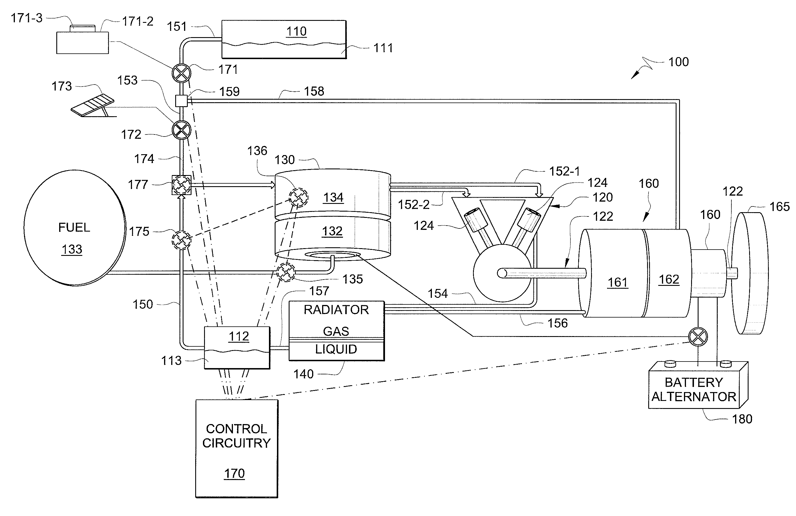
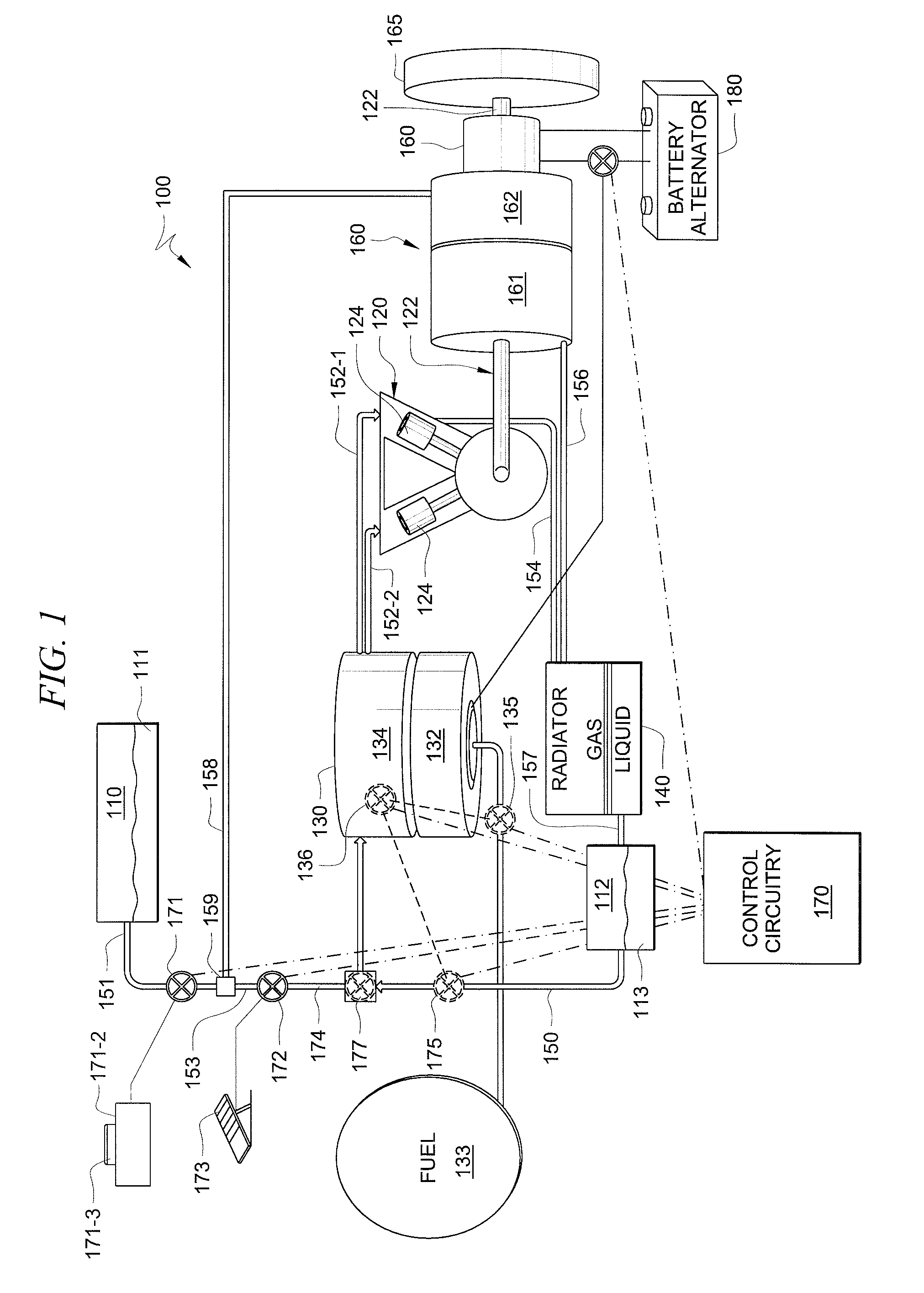
[0010]FIG. 1 is a schematic diagram of a power generation system 100 according to at least one embodiment of the present invention. In the present discussion power generation system 100 is located within a vehicle, such as an automobile; however, other usages are envisioned. Power generation unit 100 is powered by a combination of at least two fluids that are heated to achieve a gaseous state. Power generation unit 100 includes a first fluid storage vessel 110, a second fluid storage vessel 112, an engine 120, a heater 130, and a radiator 140. In one embodiment, power generation unit 100 is a closed system. By closed system, it is meant that the fluids that are used to produce the power are not intentionally vented to the outside environment. Those skilled in the art will recognize that the closed nature of system 100 does not mean that there is no leakage.

[0011]First fluid storage vessel 110 is a suitable vessel for storing a gaseous fluid such as fluid 111. Gaseous fluid 111 is a ...


PUM


Abstract

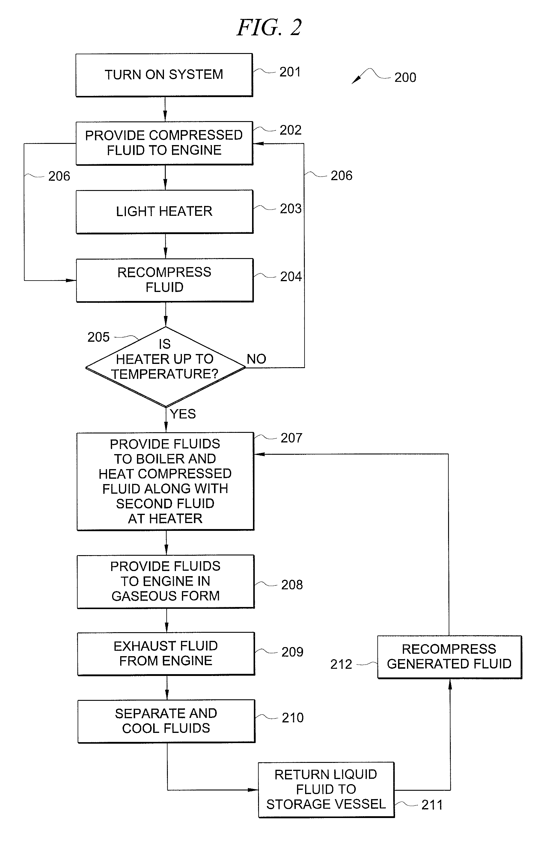
A method and system for an external combustion engine operable using at least two different fluids to provide pressure volume work to an engine. The engine is started by providing a compressed fluid at a sufficient pressure to move internal components of the engine that in turn rotate a shaft to generate power. At the same time the compressed fluid is provided to the engine, a liquid fluid is provided to a heater to be heated. The liquid fluid is heated to its boiling point and converted to gas form. Additional heat is provided to increase the pressure of this gas fluid. Once the pressure is increased to a sufficient level, the gas fluid is injected into the engine to generate power. The gas is exhausted from the engine, and is cooled and separated back into the two separate fluids. The initial compressed fluid is recompressed for later use.

Description

TECHNICAL FIELD[0001]The present invention is related to external combustion engines. More specifically, the present invention is related to an external combustion engine that is operable under two gaseous fluids.BACKGROUND OF THE INVENTION[0002]Steam engines and other external combustion engines have been known for years. They have been used on a variety of vehicles and equipment to perform work. For example, they have been used in steamboats, steam locomotives, as electrical generators and even in some of the very first automobiles. External combustion engines use a fuel source, such as wood or coal, to generate heat. Instead of burning the fuel to directly generate power, this heat is used to heat a liquid fluid such as water to its boiling point. Once the water becomes vapor, additional heat allows the pressure in a boiler to increase. It is this pressure that is needed to generate power to the engine.[0003]Once the pressure in the boiler has reached the desired pressure point, ...

Claims


Application Information

Patent Timeline
Patent Type & Authority Patents(United States)
IPC IPC(8): B60K3/02
CPCF01K15/02F01K25/08F01K25/06
Inventor BROOKMAN, MICHAEL JEFFREY
Owner AVERILL PARTNERS
Learn More