Routing control method, apparatus and system

a control method and routing technology, applied in the field of resource utilization transition prediction technique, can solve the problems of two-dimensional te reaches critical limit, dns request delay increases by 230%, and web access delay also increases by 30%, so as to achieve the effect of minimization cos

Active Publication Date: 2010-06-29
FUJITSU LTD
View PDF28 Cites 34 Cited by
  • Summary
  • Abstract
  • Description
  • Claims
  • Application Information

AI Technical Summary

Benefits of technology

[0022]Still another object of the present invention is to provide a technique for maximizing the resource utilization efficiency over the long term as well as at the time of the resource allocation request by carrying out the resource allocation taking into account the predicted utilization transition of the network resources.
[0024]Further object of the present invention is to provide a technique on network operation for reacting promptly with a traffic change or an abnormal condition, and for reducing network operation cost by systematizing the manual network operations to reduce the cost.
[0027]Basically, when the arrival of large traffic such as a large bandwidth or long holding time can be predicted, a minimum cost path is allocated to the large traffic. This improves the efficiency of the resource utilization. More specifically, it is assumed that there is a network in which N nodes are connected via a bidirectional ring as shown in FIG. 26, for example. The path connecting adjacent nodes includes a shortest path of one hop and an alternative path of N−1 hops. It is assumed here that, as shown in FIG. 27, a path setting request of a path #a carrying small traffic (bandwidth Ba, holding time ha) arrives and, immediately thereafter, a path setting request of a path #b carrying large traffic (bandwidth Bb, holding time hb) arrives. If the arrival of the path #b is not predicted, the shortest path is allocated to the path #a and an alternative path is allocated to the path #b, because the path #b is requested while the shortest path is occupied by the path #a. The resource consumption (the total sum of the used bandwidths for the used links) is represented by Baha+(N−1)*Bbhb. If the arrival of the path #b carrying the large traffic can be predicted, the alternative path is allocated to the path #a requested earlier in order to allocate the shortest path to the path #b. And then, at the time of receiving the request for the path #b, the shortest path can be allocated to the path #b. The resource consumption (the total sum of the used bandwidths for the used links) is represented by Bbhb+(N−1)*Baha. When the traffic volume of the path #b is remarkably larger than the traffic volume of the path #a, for example, when the path #a is for use in a phone call with the holding time ha of two minutes and the path #b is for use in video distribution with the holding time hb of two hours, the former allocation is overwhelmingly less efficient because the alternative path is occupied for the long holding time. Assuming Bbhb>>Baha is satisfied here in an extreme case, and Baha can be negligible, the resource consumption is (N−1)*Bahb unless the arrival of the large traffic is predicted. If it is predicted, the resource consumption is Bbhb when the shortest path is allocated to the large traffic. Therefore, the resource consumption when predicting the arrival of the large traffic becomes 1 / (N−1) comparing with the case where the arrival of the large traffic is not predicted. As described above, it becomes possible to optimize the utilization efficiency of the resources, not instantaneously, but for the long term, by predicting the future traffic transition.
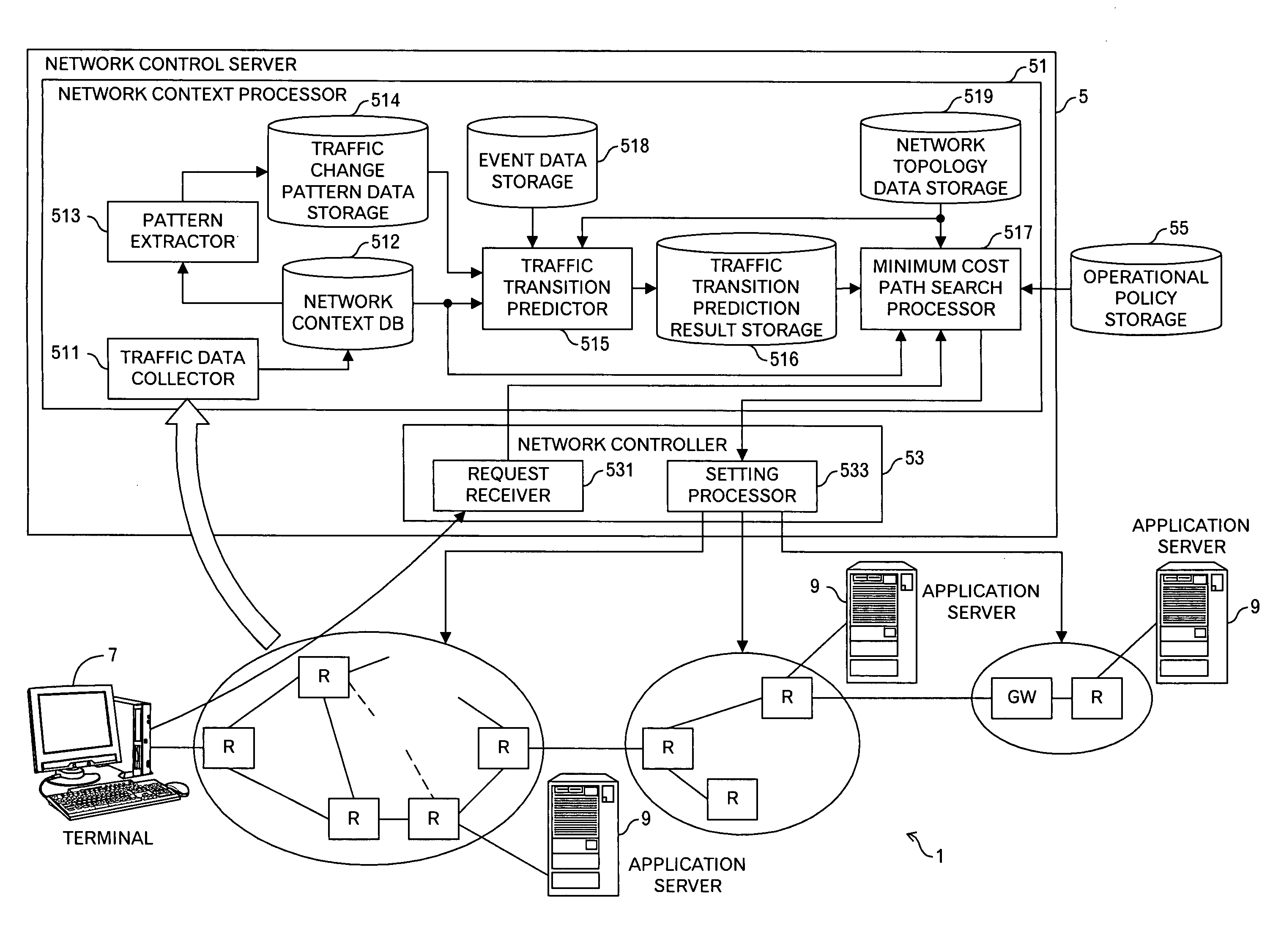
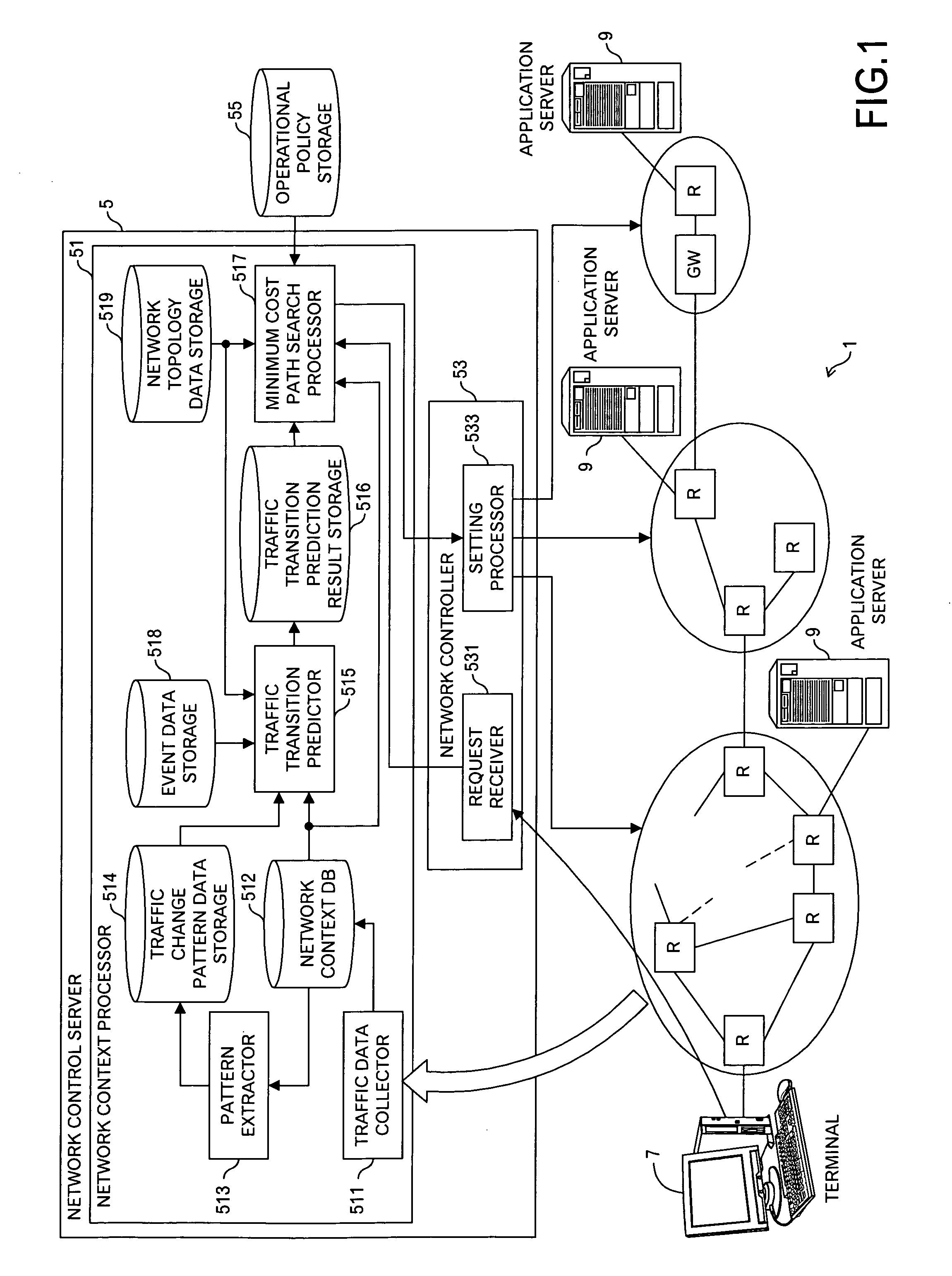
[0028]A routing control method according to a second aspect of the present invention, comprises: receiving a connection set-up request; and selecting a resource selection processing for the connection set-up request among a first processing, a second processing and a third processing. The first processing comprises: reading out predicted utilization transition data associated with the received connection set-up request from a predicted utilization transition data storage storing the predicted utilization transition data in future for each resource in a network, and selecting a resource satisfying a first predetermined condition based on the read predicted utilization transition data. The second processing comprises: selecting a resource satisfying a second predetermined condition by using data concerning a static attribute for each resource of the network, the data concerning the static attribute stored in a network data storage. The third processing comprises: selecting a resource satisfying a third predetermined condition by using current utilization status data for each resource of the network, the current utilization status data stored in a network context data storage. Thus, by switching the resource selection processing according to needs, the resource can be appropriately selected depending on the situation.
[0031]In general, the routing control method according to the first aspect of the present invention may further include: detecting the arrival of the connection set-up request for the large amount of traffic whose bandwidth or holding time is greater than a predetermined value on the basis of the predicted utilization transition data. And, the aforementioned selecting may include: obtaining a cost of each resource for a communication request for traffic other than the high volumes of traffic based on the predicted utilization transition data relating to the arrival of the communication request for the large amount of traffic to select a resource whose cost satisfies a second predetermined condition; and obtaining a cost of each resource for the communication request for the large amount of traffic by using current utilization status data for each resource of the network, which is stored in a network context data storage, or by using static attribute information stored in a network data storage to select a resource whose cost satisfies a third predetermined condition. This enables a minimum cost path to be allocated to the connection set-up request for the large amount of traffic.

Problems solved by technology

More specifically, according to the result of analyzing 12 representative attack cases, it is found that a delay in the DNS request increases by 230% and a delay in the web access also increases by 30% in the presence of malicious traffic.
Therefore, when the traffic volume in an MPLS network increases in the long term and the capacity of the entire network is insufficient, the two-dimensional TE reaches critical limit.
Therefore, consideration can be made for only bandwidth changes within holding time from the actual occurrence of the call to a time when the call will disappear, however, this technique is not intended to predict a future traffic transition before the occurrence of the call.
Therefore, this technique has a limit on improving resource efficiencies by optimization.
Furthermore, when an occurrence of planning-type congestion caused by an event is anticipated, a cache function is provided near users to reduce the load on the traffic of the core network.
Furthermore, at the time of earthquake or other abnormal conditions, blocking of calls is often used.
There has not been, however, carried out any routing using knowledge quantitatively and dynamically.
It is, however, limited to controls that are reactive and for use in protecting endpoints.
More specifically, it is not adapted to control the entire network in a preventive manner so as to satisfy a certain service criterion by using knowledge accumulated in the network.
Still further, while the document discussing the contextware service control describes a concept using a network context or a brief information flow, it does not describe how the network context should be collected and be used as a practical matter.

Method used


Image

  • Routing control method, apparatus and system
  • Routing control method, apparatus and system
  • Routing control method, apparatus and system

Examples


Embodiment Construction

A. System Outline

[0078]The outline of a system according to an embodiment of the present invention will now be described below with reference to FIG. 1. A network 1, which is an observation target and also a control target, is connected to a lot of routers R, gateways GW, and the like. Moreover, the router R is connected to terminals 7, application servers 9, and the like. Furthermore, the network 1 is connected to a network control server 5. The network control server 5 includes a network context processor 51 for carrying out a processing associated with a network context, a network controller 53 for carrying out settings for the routers R and the like in response to a connection set-up request from the terminal 7, and an operational policy storage 55 that stores an operational policy set by a network administrator or the like.

[0079]The network context processor 51 includes a traffic data collector 511 for collecting traffic data, which is a network context, from the network 1; a n...


PUM


Abstract

This invention is to enable appropriate routing based on transition prediction of network traffic. This routing control method includes: reading out predicted utilization transition data (e.g. utilization rate, or utilized bandwidth) associated with a received connection set-up request from a predicted utilization transition data storage storing said predicted utilization transition data for each resource (e.g. links between routers, or server) in a network in future; and selecting a resource satisfying a predetermined condition based on the read predicted utilization transition data. Thus, by using said predicted utilization transition data, an appropriate resource is identified in accordance with future time transition of the resource utilization rate, for example, and thereby, appropriate routing is possible. For example, when a link that a traffic volume will increase after a predetermined time exists, it is possible to judge that such a link is not used even when there are a lot of available bandwidths now.

Description

TECHNICAL FIELD OF THE INVENTION[0001]The present invention relates to a prediction technique of resource utilization transition in a network, and a routing technique using a predicted result of the resource utilization transition.BACKGROUND OF THE INVENTION[0002]In today's situation where various crimes using a network such as a DDoS attack, hacking, and the like are increasing and the problem is becoming increasingly serious, there is a growing need for information security. Focusing on that traffic characteristics change during a DDoS attack, hacking, or the like, many researches are being conducted on methods of detecting abnormalities by observing network traffic. For example, refer to “Technical Research on High-traffic Observation and Analysis Method (Information Security Guard R&D Evaluation Services)” in 15 Jokei No. 1632, April / 2004, Information-technology Promotion Agency (IPA).[0003]More specifically, according to the result of analyzing 12 representative attack cases, i...

Claims


Application Information

Patent Timeline
Patent Type & Authority Patents(United States)
IPC IPC(8): H04J3/14H04L45/42H04M3/00
CPCH04L12/2602H04L41/147H04L41/5054H04L43/00H04L41/5035H04L41/0896H04L41/5003H04L43/0894H04L43/0882H04L43/091
Inventor KATOH, MASAFUMIKATO, TSUGUOYAMADA, HITOSHI
Owner FUJITSU LTD
Why Eureka
Try Eureka