
Apparatus and method of fabricating a door

a technology of door frame and assembly method, applied in the field of doors, can solve the problems of increasing shipping costs, increasing the final cost to an end user, and the cost of finished doors that include the cost of these materials, so as to minimize labor and waste, reduce costs, and facilitate manufacturing

Inactive Publication Date: 2010-07-06
TURNER DANIEL S +2
View PDF6 Cites 8 Cited by
  • Summary
  • Abstract
  • Description
  • Claims
  • Application Information

AI Technical Summary

Benefits of technology

[0015]It is a general object of the present invention to provide a door having a door light at a low cost which is easy to manufacture.
[0016]It is another general object of the present invention to minimize the labor and waste created by cutting out a door light from a door after door skins have been assembled and foam insulation has been injected into a cavity formed between the door skins, wherein the waste is a recyclable product.
[0017]It is yet another object of the present invention to minimize associated shipping costs for shipping a door from raw door manufacturers to finished door manufacturers by providing a door having a lower weight.

Problems solved by technology

In fact, waste products of this type are typically considered hazardous waste due to the presence of the foam, and therefore, special waste disposal considerations must be taken into account.
Although the finished door does not include the above described waste material, the finished door cost does include the cost of these materials.
The uncut doors weigh more than cut doors and therefore shipping costs are also increased thereby raising the final cost to an end user.
Heretofore, tradeoffs between material waste generated during manufacture and cost were required.

Method used


Image

  • Apparatus and method of fabricating a door
  • Apparatus and method of fabricating a door
  • Apparatus and method of fabricating a door

Examples


Embodiment Construction

[0044]At the outset, it should be appreciated that like drawing numbers on different drawing views identify identical, or functionally similar, structural elements of the invention. While the present invention is described with respect to what is presently considered to be the preferred aspects, it is to be understood that the invention as claimed is not limited to the disclosed aspects.

[0045]Furthermore, it is understood that this invention is not limited to the particular methodology, materials and modifications described and as such may, of course, vary. It is also understood that the terminology used herein is for the purpose of describing particular aspects only, and is not intended to limit the scope of the present invention, which is limited only by the appended claims.

[0046]Unless defined otherwise, all technical and scientific terms used herein have the same meaning as commonly understood to one of ordinary skill in the art to which this invention belongs. It should be appr...


PUM

PropertyMeasurementUnit
ninety degree anglesaaaaaaaaaa
perimeteraaaaaaaaaa
pressureaaaaaaaaaa

Abstract

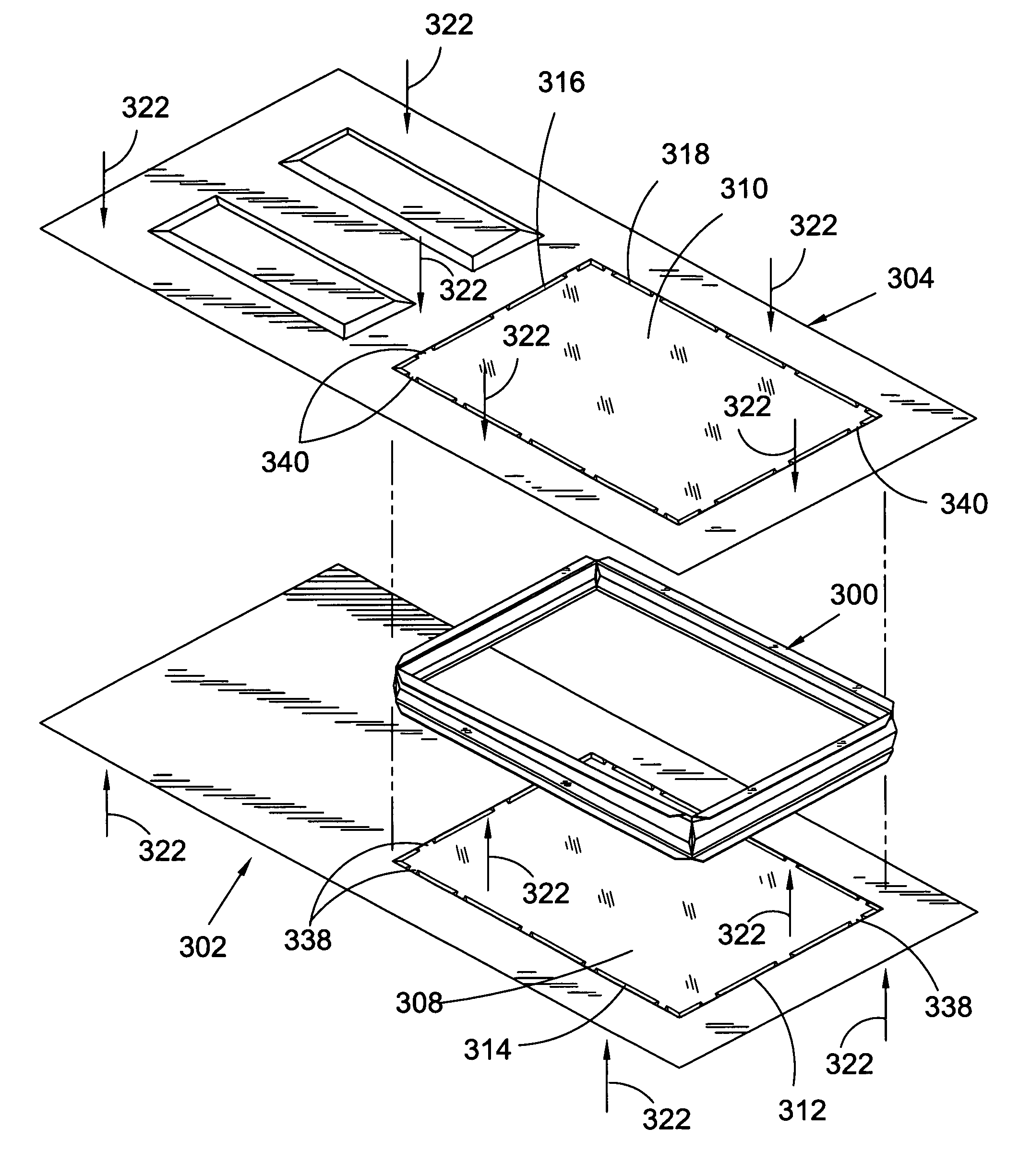
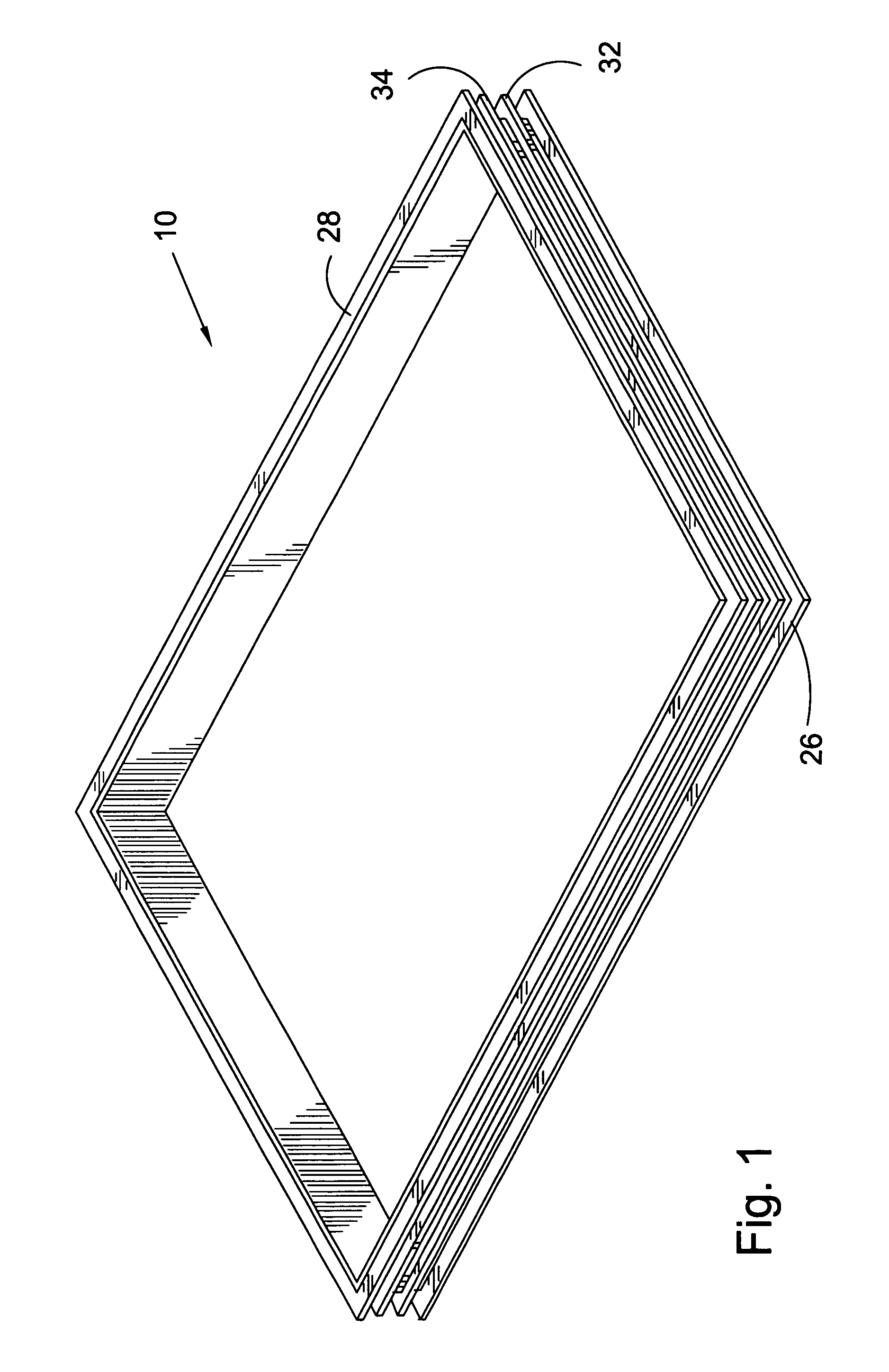
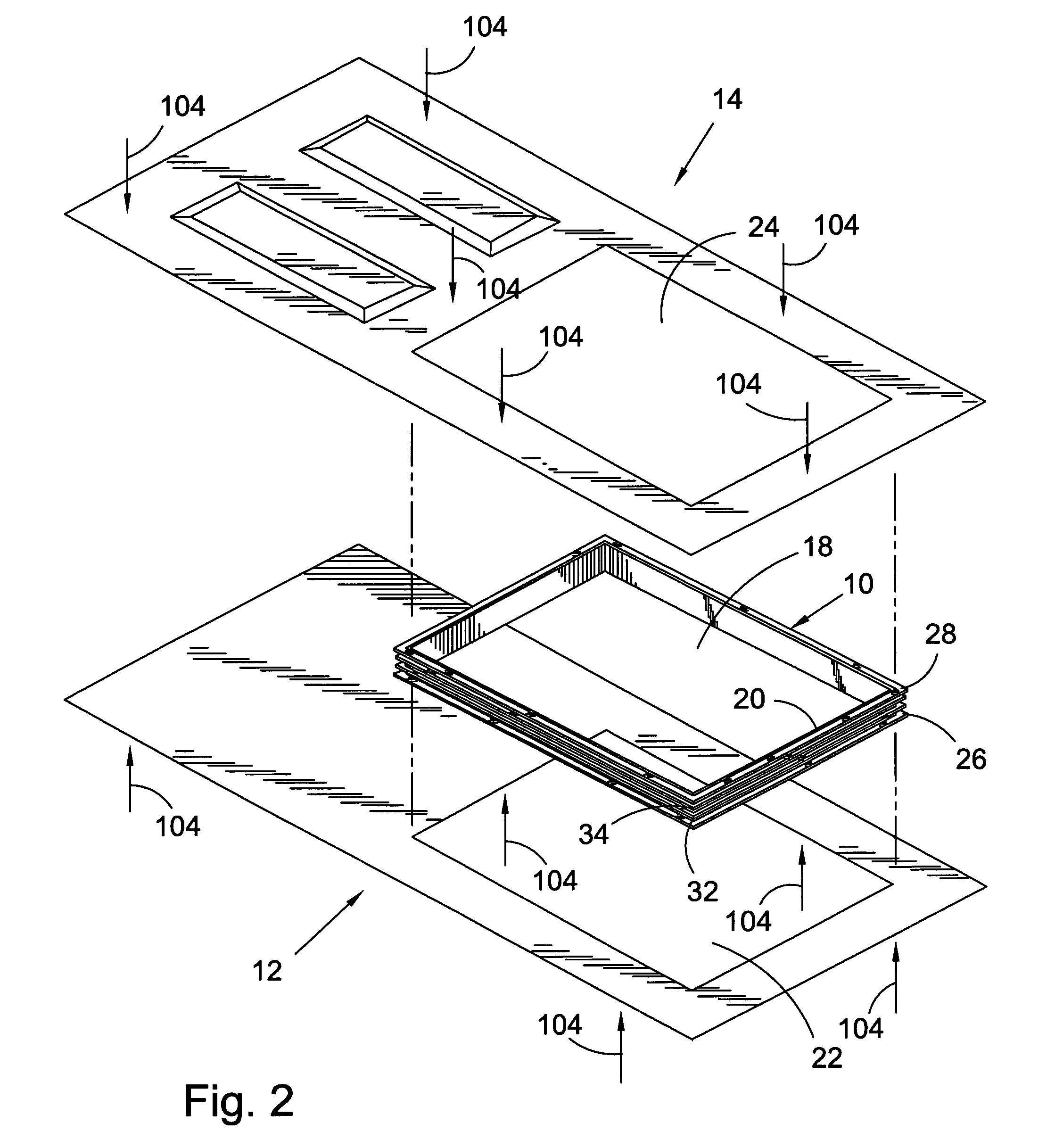
A method for fabricating a door having a window, the door having a first door skin and a second door skin, the method including the following steps in the order named: forming a first door light opening perimeter having a first plurality of tabs arranged about the first door light opening perimeter, wherein the first door light opening perimeter defines a first door light portion; forming a second door light opening perimeter having a second plurality of tabs arranged about the second door light opening perimeter, wherein the second door light opening perimeter defines a second door light portion; positioning the first door skin on a first press; positioning an insert in aligned registration with the first plurality of tabs; positioning the second door skin over the insert, wherein the second plurality of tabs are in aligned registration with the insert, and the first door light opening perimeter is aligned with the second door light opening perimeter; applying pressure with the first press to secure the first and second door skins with the insert; injecting a foam into a first cavity formed between the first skin outside the first door light portion, the second door skin outside the second door light portion and the insert; and, removing the first and second door light portions.

Description

CROSS-REFERENCE TO RELATED APPLICATIONS[0001]This application is a Continuation-in-Part of application Ser. No. 11 / 786,919, filed on Apr. 13, 2007 now abandoned, which application is incorporated herein by reference.FIELD OF THE INVENTION[0002]The invention broadly relates to doors, more specifically to lights for doors, and even more particularly to lights for doors constructed from complimentary door skins. The invention also broadly relates to a method of fabricating a door with a door light perimeter defined within the door skins before assembly and arranged to accommodate a window. The invention also relates to an apparatus for carrying out the method of fabrication.BACKGROUND OF THE INVENTION[0003]Typically, doors constructed of steel or fiberglass comprise two molded door skins forming the front and back surfaces of the door. The door skins are joined together and filled with an expanding foam core which provides insulation, e.g., thermal and sound, and increases structural i...

Claims


Application Information

Patent Timeline
Patent Type & Authority Patents(United States)
IPC IPC(8): B23P17/00B21D39/03E06B3/964E04C2/54B23P15/12B32B3/00
CPCB29C44/1233E06B3/5892E06B2003/7023Y10T29/49826Y10T428/233Y10T29/49616Y10T428/13Y10T29/49625
Inventor TURNER, DANIEL S.MCCONNELL, II, COLIN S.EBY, MONTGOMERY L. G.
Owner TURNER DANIEL S
Learn More