Torque anchor and method for using same

a technology of torque anchors and torque rods, applied in the field of torque anchors, can solve the problems of extra wear on such tools, damage to the adjacent tubing,

Active Publication Date: 2010-07-06
TAZCO HLDG
View PDF13 Cites 19 Cited by
  • Summary
  • Abstract
  • Description
  • Claims
  • Application Information

AI Technical Summary

Problems solved by technology

This system can provide a pinch point that can damage tubing running adjacent to the torque anchor.
In addition, this system by virtue of the main body of the torque anchor engaging with the well casing will similarly cause tools such as the stator of a PC pump to be biased against the well casing causing extra wear on such tools.

Method used


Image

  • Torque anchor and method for using same
  • Torque anchor and method for using same
  • Torque anchor and method for using same

Examples


Embodiment Construction

[0026]In accordance with the invention and with reference to the figures, embodiments of a torque anchor 10 are described.

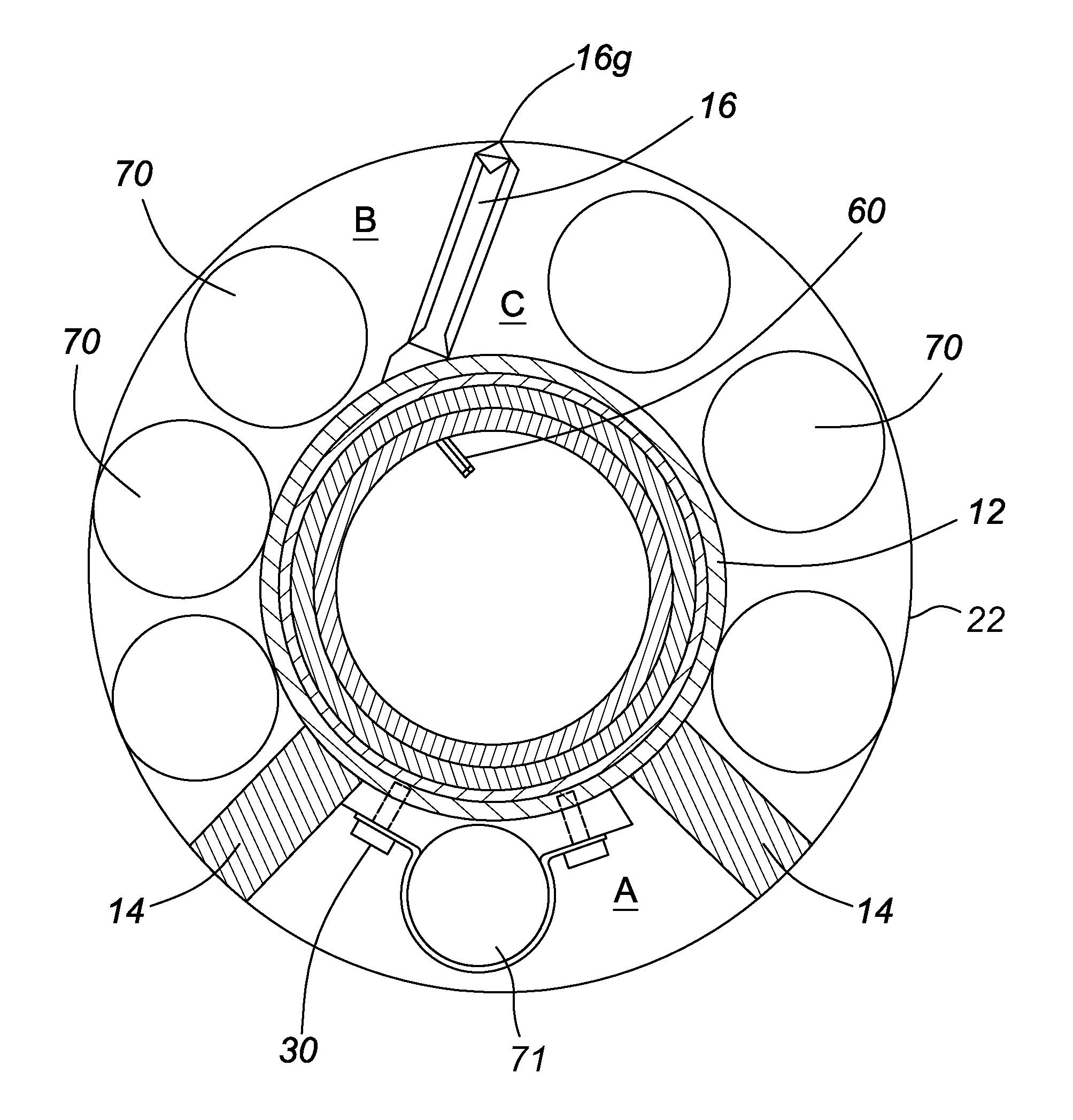
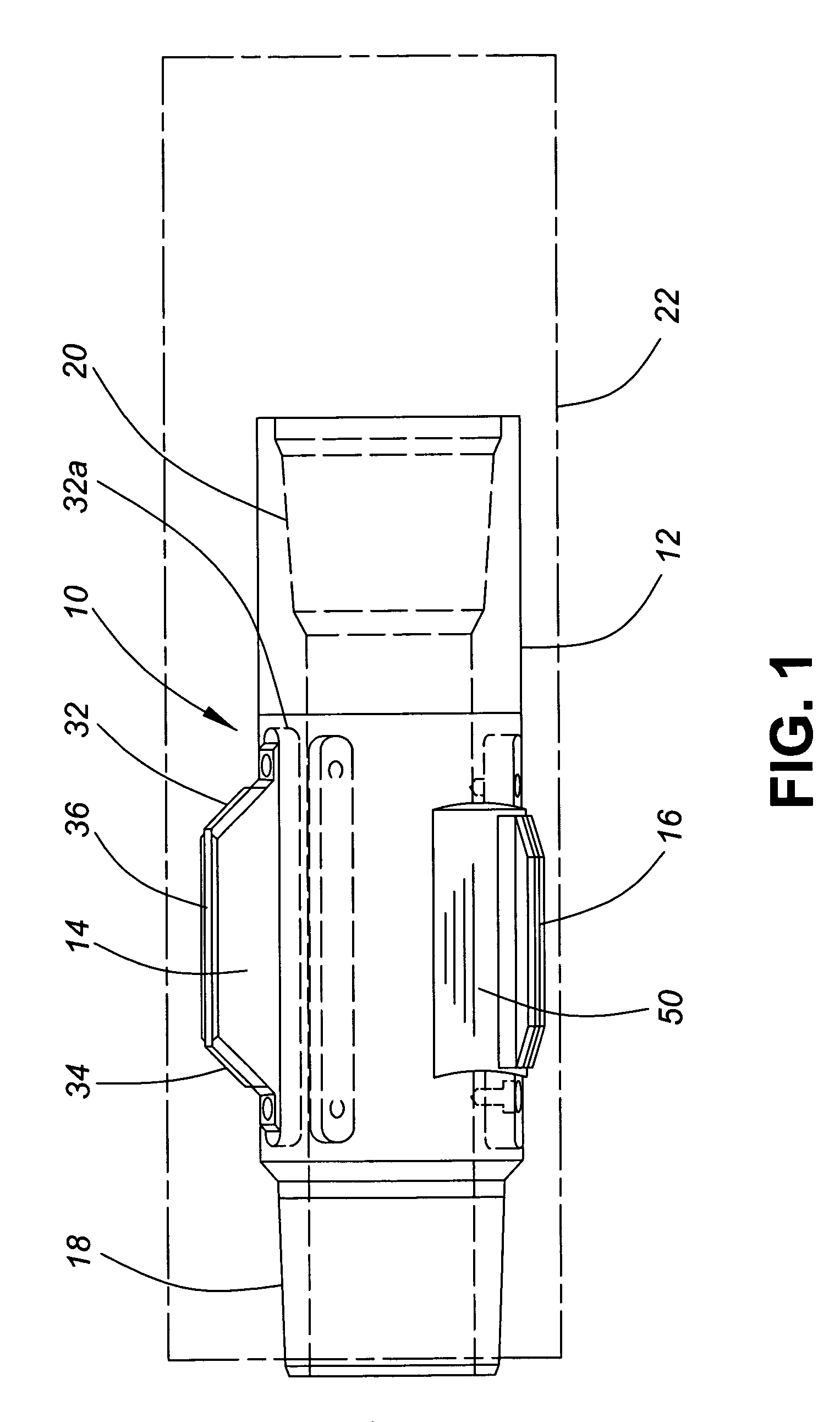
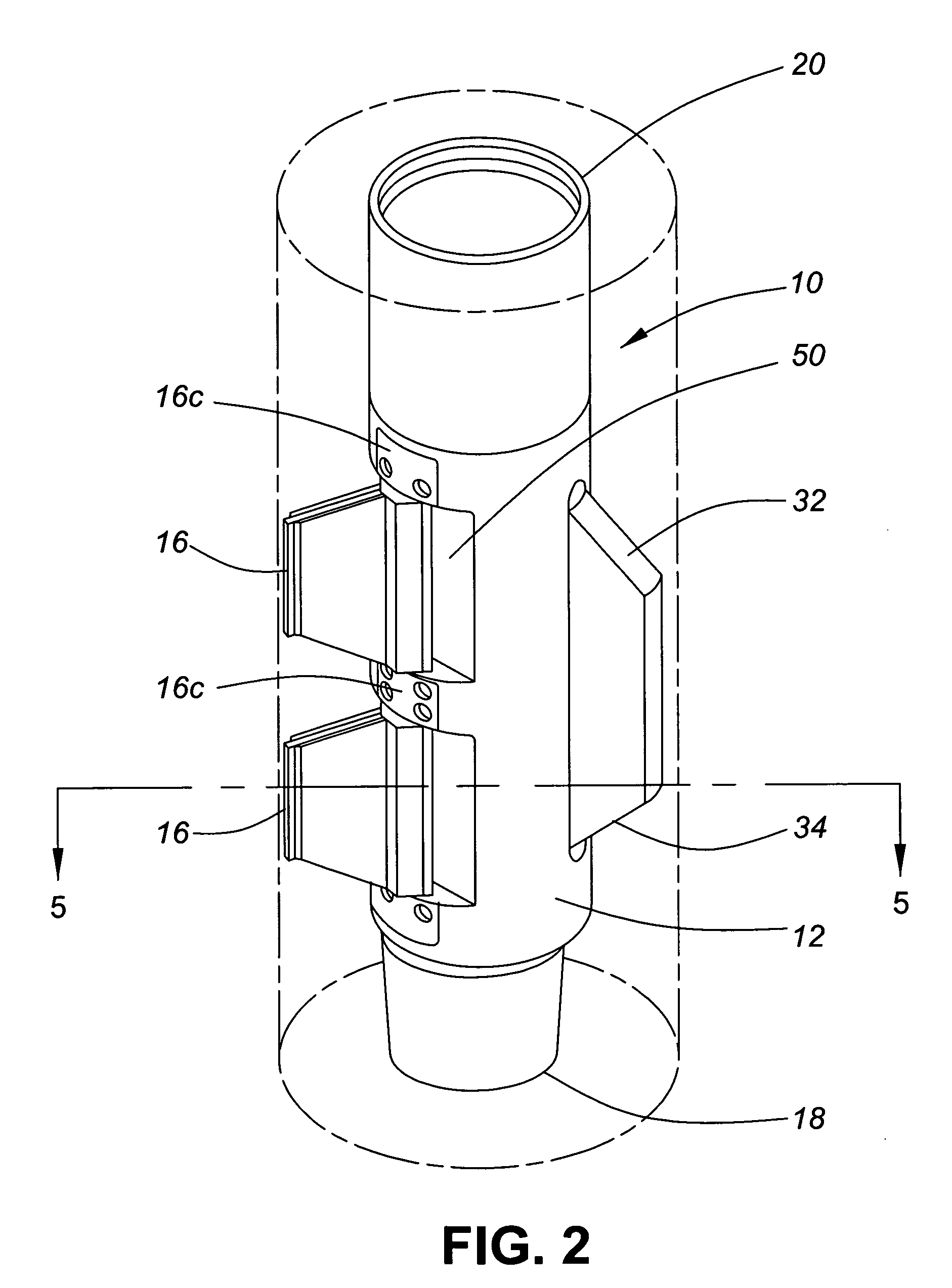
[0027]With reference to FIGS. 1-5, embodiments of a torque anchor 10 are shown in two perspective views (FIGS. 1 and 2) and cross-sectional views (FIGS. 3, 4 and 5). The torque anchor generally includes a body 12 on which at least one rigid stabilizing slip, (preferably two) 14 and one outwardly biased and pivotable slip 16 are mounted. The body 12 includes appropriate male 18 and female 20 connectors to allow the torque anchor to be connected to a progressive cavity (PC) pump stator or tubing string (not shown) as known to those skilled in the art.

[0028]When mounted to a PC pump stator or tubing string, counter-clockwise rotation (as viewed from above) of the tubing string will permit counter-clockwise rotation of the torque anchor, PC pump and tubing string within well casing 22 (or well bore). Clockwise rotation of the tubing string (as viewed from above) will...


PUM


Abstract

A torque anchor for use with progressive cavity pumps (PC Pumps) for preventing rotation of the PC Pumps and any related tool string within a well bore, possessing a connector constructed and adapted to connect a tube, which in a preferred embodiment is a diluent cable, between the two fixed slips. A method is also recited for running coiled tubing or a diluent cable downhole using the torque anchor.

Description

FIELD OF THE INVENTION[0001]The invention describes a torque anchor for use with progressive cavity pumps (PC pumps) for preventing rotation of the PC pumps and any related tool string and tubing within a wellbore. The torque anchor includes at least one fixed rigid slip and one pivotable slip that in combination enhance the ability of the torque anchor to remain centered within wellbore casing and provide space between the torque anchor and wellbore casing for other tubing and / or other cabling or instruments to be run within the well and / or facilitate the passage of sand and other substances indigenous to many well formations past the torque anchor.BACKGROUND OF THE INVENTION[0002]During oil-well production, in-line pumps such as progressive cavity pumps are used to pump oil from the well bore to the surface. A progressive cavity pump system includes a surface driven rotor mounted within a downhole stator that is rotationally secured to production casing so as to prevent rotation o...

Claims


Application Information

Patent Timeline
Patent Type & Authority Patents(United States)
IPC IPC(8): E21B43/00
CPCE21B23/01
Inventor MOORE, EDWARD L.
Owner TAZCO HLDG
Why Eureka
Try Eureka