Pipes coupling with integrated grip

a technology of pipe coupling and grip, which is applied in the direction of hose connection, fluid pressure sealing joint, sleeve/socket joint, etc., can solve the problems of limiting the application of this type of coupling, difficult field application of high axial force, and inability to achieve the best valve for all applications. , to achieve the effect of reducing distan

Active Publication Date: 2010-07-06
KRAUSZ IND
View PDF26 Cites 51 Cited by
  • Summary
  • Abstract
  • Description
  • Claims
  • Application Information

AI Technical Summary

Benefits of technology

[0027]e) clamping elements to allow clamping of said housing around said pipes, preventing leakage of fluid carried by said pipes and preventing axial separation therebetween.
[0029]In a further preferred embodiment said housing is provided with a pair of end extensions to allow clamping by reducing the distance between said extensions.
[0033]It will thus be realized that the novel device of the present invention serves to overcome the limitations of prior-art pipe couplings and to provide a coupling which makes allowance for variations in the pipes to be connected.

Problems solved by technology

Thus, there is no best valve for all applications.
In many applications welding is time-consuming, prohibited or impossible, which limits the applications of this type of coupling.
Application of a high axial force in the field is difficult, and there is no way either to further tighten or to open the coupling.
The same remarks apply to the coupling disclosed by Readman in U.S. Pat. No. 6,595,559, which has an additional disadvantage in that the flow of fluid in the pipe is somewhat restricted.
The device has a quick-acting closure, but no protection against axial separating forces, and in use it is difficult to prevent fluid leakage due to gaps between the two bands.
The device would not be usable for large diameter steel pipes as the assembly forces required would be very large and also the coupling can not be tightened to prevent leakage.
The design seen in U.S. Pat. No. 6,739,630 to Riedy is unsuitable for large diameter pipes as it requires one end of one of the pipes to carry an external threw thread.
Furthermore there remains the difficult task of revolving the large diameter nut sleeve while preventing revolution of the pipe carrying the male thread in order to apply the coupling.
Provision is made for deterring axial separation, but sealing this type of clamp against leakage is problematic due to the gap between the ends of the band.
There is however no way of tightening the seal and this type of coupler is unsuited for large diameter pipes and cannot handle pipe diameter variations.
The thin seal used and its indirect manner of applying pressure to the outer surface of the pipes appear to be the weak points of this design.
However the design does not make provision for substantial outer diameter variations and the locking mechanism would be difficult to operate if applied to large diameter pipes.
Any intrusion into the inner space of a pipe is of course detrimental in increasing the hydraulic resistance of the pipeline.

Method used


Image

  • Pipes coupling with integrated grip
  • Pipes coupling with integrated grip
  • Pipes coupling with integrated grip

Examples


Embodiment Construction

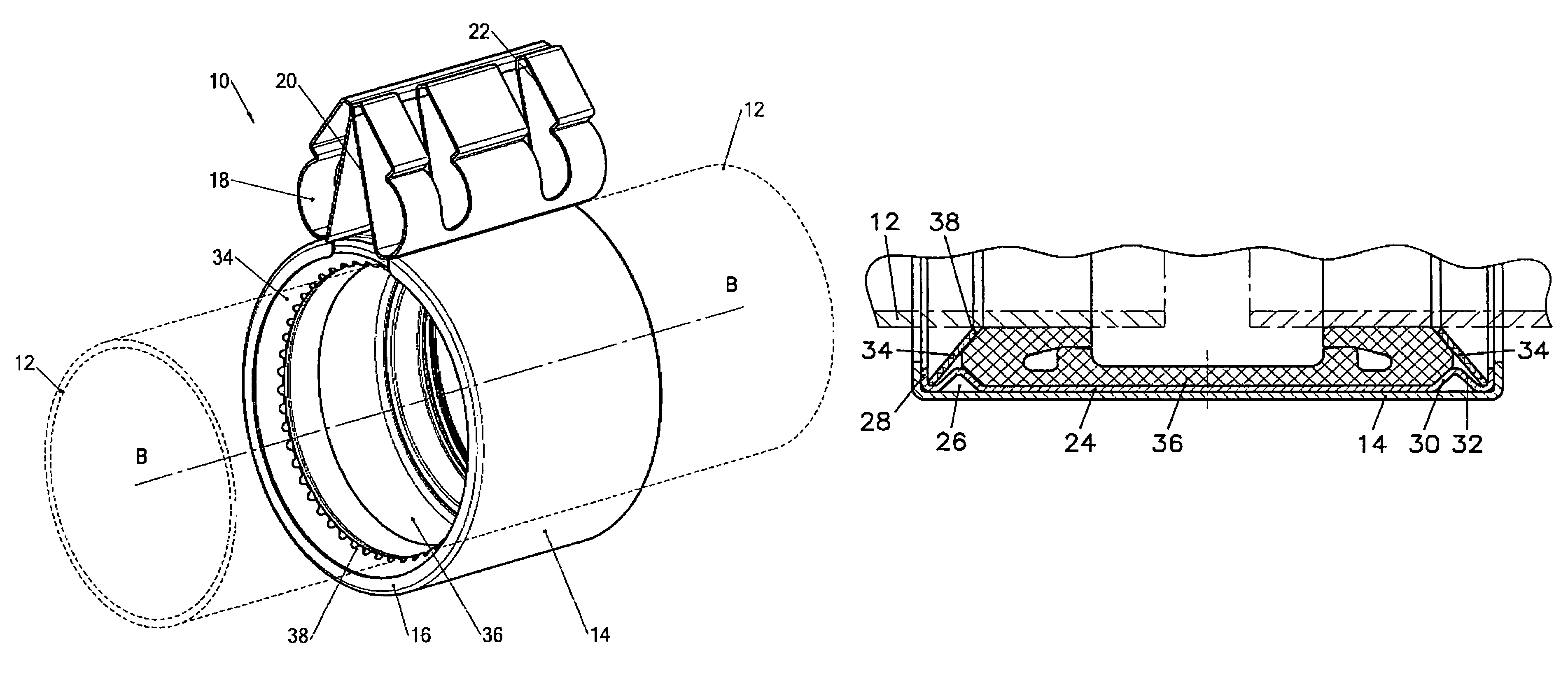
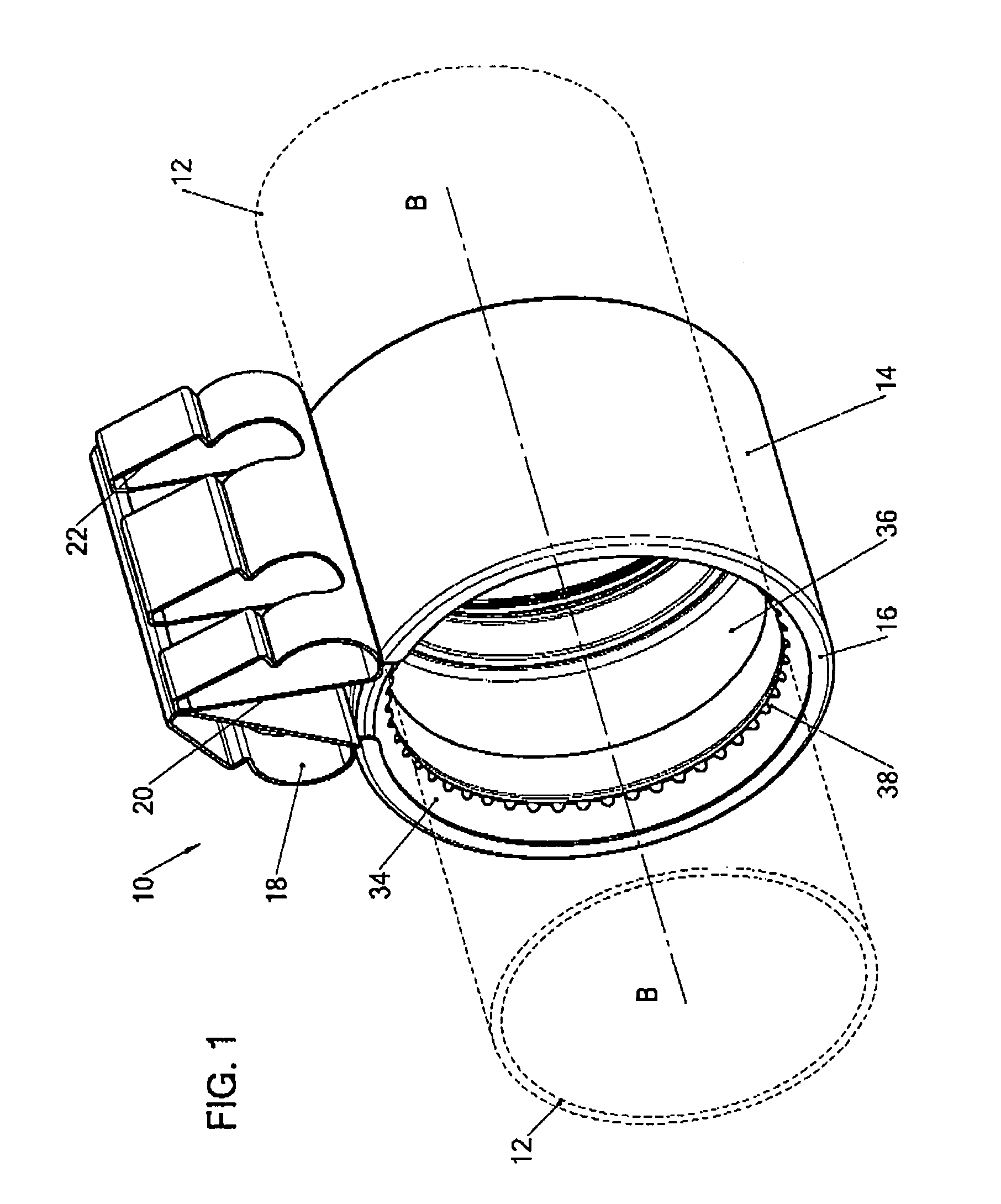
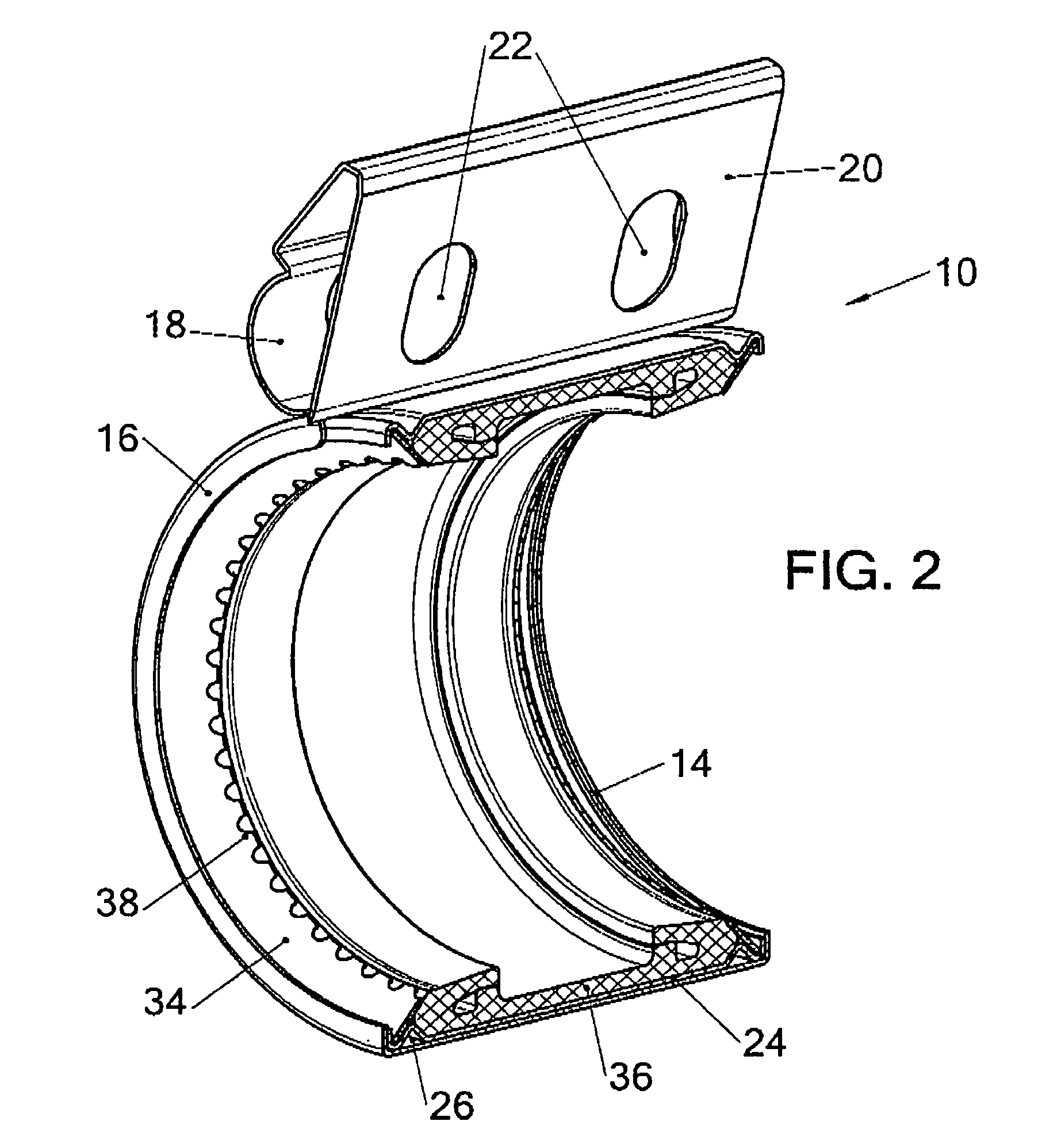
[0043]There is seen in FIGS. 1 and 2 an improved band-clamp releasable coupling 10 for mechanical and hydraulic linear interconnection of the ends of two pipes 12.

[0044]An outer housing 14 of cross-section resembling a wide, low-wall channel can suitably be made of stainless steel. The low walls 16 of the channel face the center BB of the coupling. The housing 14 is curved to be slightly larger than the pipe diameter. The extremities 18 of the housing channel 14 are bent and formed so that a pair of end extensions 20 is obtained which allow clamping. Apertures 22 for screw clamping are seen in the end extensions 20. Referring now also to FIG. 3 where details are seen to better effect, a low-wall inner channel 24 is curved to fit snugly into the outer housing 14. The inner channel 24 is provided with two spaced-apart inwardly-facing projections 26 adjacent to each of the inner channel walls 28. Each projection 26 has a first sloping side 30 axially facing the line of pipe abutment. A...


PUM


Abstract

A band coupling for straight line interconnection of flangeless pipes and a built in pipe grip mechanism to resist axial separation forces is provided. The band-clamp coupling comprises an outer housing of cross-section resembling a wide, low-wall channel, the walls thereof facing the center of the pipes, and a low-wall inner channel fitting into the outer channel. The inner channel being provided with spaced-apart inwardly-facing projection adjacent to each of the inner channel walls, each projection having a first sloping side axially facing the line of pipe abutment and a second sloping side axially facing away from the line of pipe abutment. A sloped internally-toothed grip washer is disposed along each of the projection second sides; and a seal member is disposed inside the inner channel and extending along the major portion of the width thereof to abut both the first sides axially facing the line of pipe abutment.

Description

CROSS-REFERENCE TO RELATED APPLICATION[0001]This application is a Convention Filing of Israel Patent Application No. 174110, filed Mar. 5, 2006, which is hereby incorporated by reference in its entirety.FIELD OF THE INVENTION[0002]The present invention relates to the interconnection of co-axial pipes.[0003]More particularly, the invention provides a band coupling for straight line interconnection of flangeless pipes and provides a built in pipe grip mechanism to resist axial separation forces.BACKGROUND OF THE INVENTION[0004]As the requirement for straight-line interconnection of pipes is widespread, a large market exists for pipe couplings for this purpose, and thousands of different designs have been disclosed. Some have been commercially developed as a solution for closely-defined requirements. In choosing a coupling much depends on factors such as the material of the pipe, whether an external anchor (such as a flange) is available, pipe diameter and variation of said diameter ex...

Claims


Application Information

Patent Timeline
Patent Type & Authority Patents(United States)
IPC IPC(8): F16L21/02
CPCF16L17/04F16L21/005F16L21/08
Inventor KRAUSZ, ELIEZERCHIPROOT, AVI
Owner KRAUSZ IND
Why Eureka
Try Eureka