Device for guiding surgical sewing material to a needle

a sewing material and needle technology, applied in the field of needle guiding devices, can solve the problems of sewing material pushing forward toward the needle, large transport devices, and difficult to control, and achieve the effect of preventing kinks in sewing materials

Inactive Publication Date: 2010-07-06
KARL STORZ GMBH & CO KG
View PDF33 Cites 49 Cited by
  • Summary
  • Abstract
  • Description
  • Claims
  • Application Information

AI Technical Summary

Benefits of technology

[0008]Because the invention proposes to design the guide channel so that it can be mechanically locked, at least in sections, the piling up and protrusion of the sewing material out of the guide channel is prevented. Because of the natural stiffness of the sewing material, it is sufficient to lock the guide channel only in some portions. The remaining area between two locked areas of the channel can be designed so that repeated piling up of the sewing material is prevented.
[0010]It is proposed with a preferred embodiment of the invention that the at least one locking element should have at least one blocking element to lock the guide channel above the sewing material, at least in sections, This blocking element positioned above the sewing material blocks any possible piling up of the sewing material and thus allows additional forward and reverse pushing of the sewing material along the guide channel. Every locking element advantageously has two blocking elements that are contiguous to one another.
[0011]The invention proposes, for the configuration of the blocking elements, that they should preferably be configured as O-rings consisting of a plastic or rubber material. Configuring the blocking elements as two contiguous O-rings of an elastic material, such as a plastic or rubber material for instance, has the advantage that the sewing material can be pressed from above between the mutually contiguous blocking elements forward into the guide channel, without being obliged to open the lock element and / or the blocking element in a separate operational step.
[0014]It can be made easier to insert the threaded bolt correctly aligned into the gripping portion if, on the rotatable shaft, at least one positioning element is configured that interacts with a corresponding positioning element in the gripping portion. The positioning element configured on the rotatable shaft is advantageously configured as a longitudinal rib, which can be inserted into a corresponding longitudinal groove in the gripping portion so that an even alignment of the groove and the guide channel is constantly ensured.
[0019]It is further proposed with the invention that on the distal end of the gripping portion a gripping hollow is configured for clamped gripping of the sewing material. The gripping hollow here is configured in such a way that it is adjusted to the position and shape of the thumb of the hand holding the device. Holding the sewing material so that it is at times clamped is advantageous in order to prevent unintentionally pulling the sewing material out of the needle.
[0020]Finally, it is proposed with the invention that on the floor of the gripping hollow a guide groove is configured to insert the sewing material, first in order to hold the sewing material in the correct alignment even with clamped gripping of the sewing material, and second in order to prevent kinks in the sewing material.

Problems solved by technology

The disadvantage of this known guide device is the fact that the construction of the transport device is very large and in addition operation of the transport device requires some practice.
This otherwise very reliable device has the disadvantage that the sewing material pushed forward toward the needle, because of its own stiffness, tends to pile up and to protrude upward out of the guide channel as soon as a slightly greater resistance occurs in the forward area of the sewing material, for instance when it is introduced into the needle.
However, as soon as the sewing material protrudes out of the guide channel, further advancement of the sewing material toward the needle is impossible.

Method used


Image

  • Device for guiding surgical sewing material to a needle
  • Device for guiding surgical sewing material to a needle
  • Device for guiding surgical sewing material to a needle

Examples


first embodiment

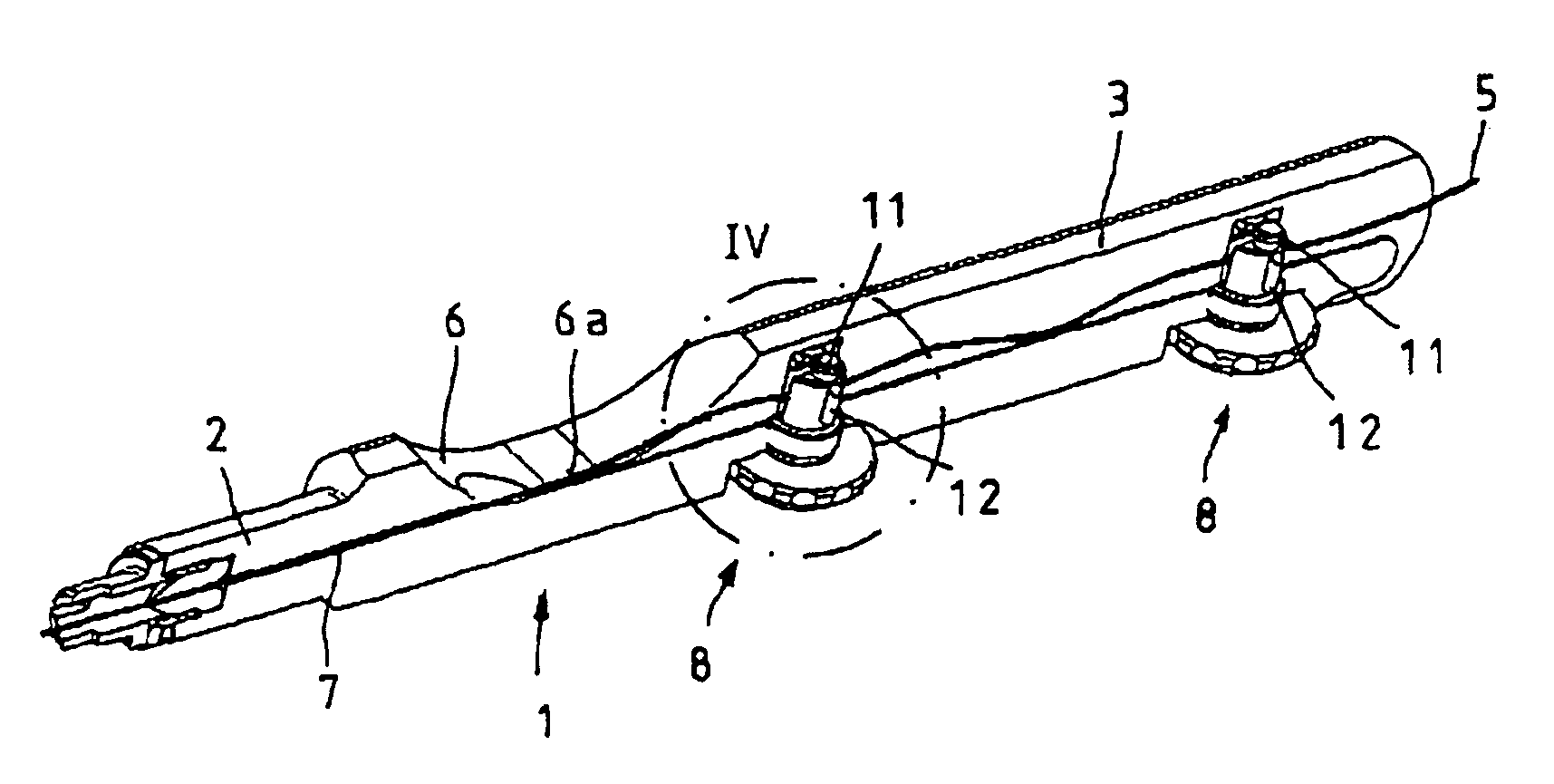
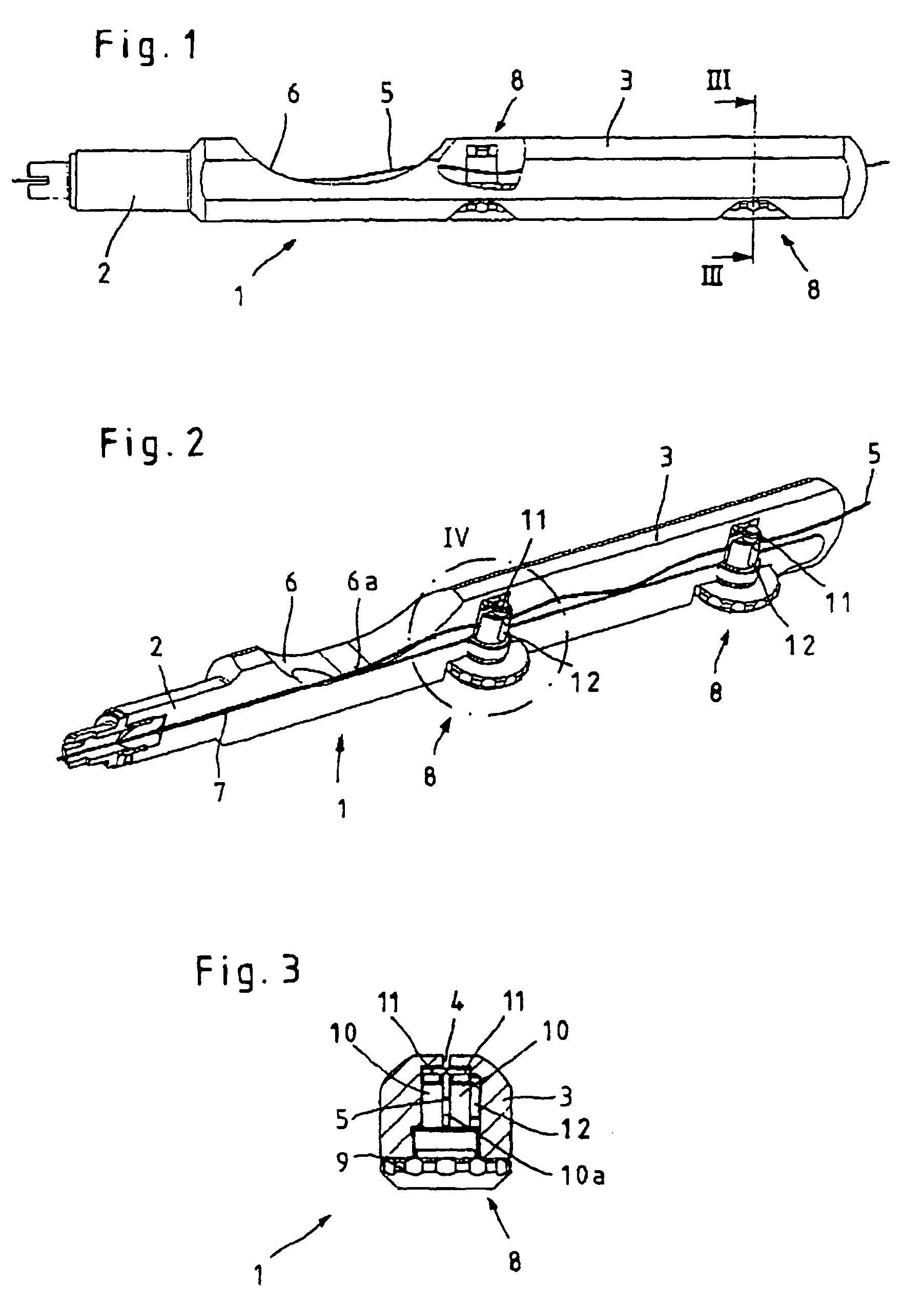
[0031]In the first embodiment shown in FIGS. 1 to 4, this locking of the guide channel 4 is performed by two locking elements 8 positioned in the guide channel 4, by means of which elements the sewing material 5 can be held on the guide channel 4. As can be seen in particular from FIGS. 2 and 4, the locking elements 8 are configured as threaded bolts that can screw into the gripping portion 3 of the shaft 1 from the side opposite the opening of the guide channel 4. The threaded bolt that forms the locking element 8 consists here essentially of a base body 9 equipped with an outer thread 9a as well as a shaft 10 that is positioned so that it can rotate freely on the base body 9 and that is divided into two shaft shanks by a vertical groove 10a corresponding to the guide channel 4.

[0032]The sewing material 5 is actually retained in the guide channel 4 or in the groove 10a of the shaft 10 by means of blocking elements 11 positioned on the free ends of the shaft shanks, which blocking e...

second embodiment

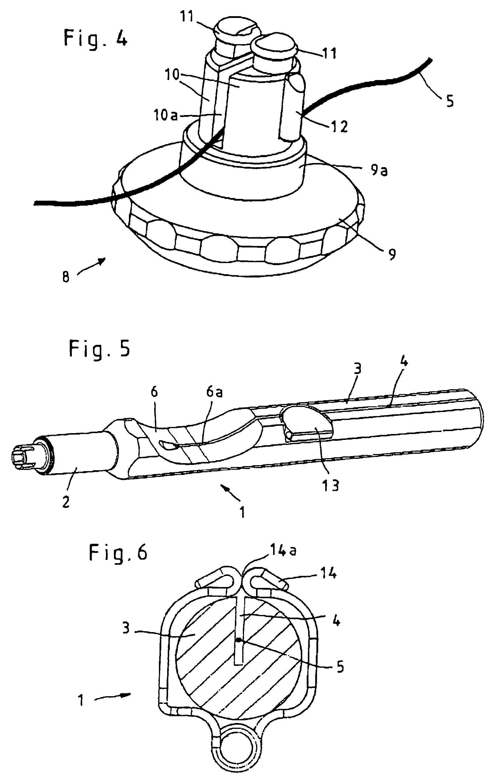
[0035] illustrated in FIG. 5, this locking element is configured as a covering lid 13 rotatably mounted on the gripping portion 3. To insert the sewing material 5 into the guide channel 4, the covering lid 13 is flipped open and the sewing material 5 is inserted from above into the guide channel 4. During operation the covering flap 13 is held in the locked position by the user's hand, which grips around the shaft 1 of the device, so that any unintentional protrusion of the sewing material 5 out of the guide channel 4 is prevented. According to an alternative embodiment the covering lid 13 can also be configured in such a way that it is pre-weighted by a spring element in the closing direction so that the covering lid 13 is configured as a self-securing snapping device.

third embodiment

[0036]In the third embodiment, illustrated in FIG. 6, the covering of the guide channel 4 is ensured by a clamp 14 that can be secured on the gripping portion 3 and surrounds it and, as illustrated, can be configured as a spring element. Alternatively to the configuration as a clamp 14, it is possible to configure the covering as a sleeve that is essentially form-fitted and can slide onto the gripping portion 3. The clamp 14 or the sleeve, after insertion of the sewing material 5 into the guide channel 4, is mounted on the gripping portion 3 of the shaft 1 in order to lock the guide channel 4 on its surface and to prevent unintentional protrusion of the sewing material 5 out of the guide channel 4. In the case of the clamp 14, however, it is also possible to apply it on the gripping portion 3 of the shaft 1 before the insertion of the sewing material 5 into the guide channel 4 and to guide the sewing material 5 into the guide channel 4 through an opening 14a of the clamp 14 position...


PUM


Abstract

The invention relates to a device for guiding surgical sewing material to a needle, having a shaft on whose distal end the needle can be secured and whose proximal end is configured as a gripping portion equipped with an open guide channel for the sewing material that is to be guided. To create a device that is of simple construction and ensures reliable transport of the sewing material to the needle, the invention proposes that the guide channel can be locked mechanically, at least in sections.

Description

CROSS-REFERENCE TO RELATED APPLICATIONS[0001]The present application claims priority of German patent application No. 10 2005 015 687.8 filed on Apr. 6, 2005, the content of which is incorporated herein by reference.FIELD OF THE INVENTION[0002]The invention relates to a device for guiding surgical sewing material to a needle, having a shaft on whose distal end the needle can be secured and whose proximal end is configured as a gripping portion equipped with an open guide channel for the sewing material that is to be guided.BACKGROUND OF THE INVENTION[0003]Devices of this type serve to guide the surgical sewing material, starting from a spool of thread, to a surgical needle configured as a rule at least partly as a hollow needle.[0004]U.S. Pat. No. 2,808,055 describes a device for guiding surgical sewing material that consists of a gripping portion and a transport device positioned in the gripping portion, by means of which the sewing material can be guided to the needle by forward a...

Claims


Application Information

Patent Timeline
Patent Type & Authority Patents(United States)
IPC IPC(8): A61B17/04
CPCA61B17/04A61B17/0483A61B17/0485
Inventor OBERLAENDER, MARTINSAUER, MICHAEL
Owner KARL STORZ GMBH & CO KG
Why Eureka
Try Eureka