Photoluminescence liquid crystal display

a liquid crystal display and photoluminescence technology, applied in the field of photoluminescence liquid crystal display, can solve the problems of reducing the light use efficiency of conventional lcd, and achieve the effect of increasing the amount of light loss and improving the light use efficiency

Inactive Publication Date: 2010-07-06
SAMSUNG ELECTRONICS CO LTD
View PDF2 Cites 42 Cited by
  • Summary
  • Abstract
  • Description
  • Claims
  • Application Information

AI Technical Summary

Benefits of technology

[0009]Example embodiments provide a photoluminescence liquid crystal display (LCD) that has an improved light use efficiency by removing an optical component that causes an increased amount of light loss.

Problems solved by technology

For example, the conventional LCD may have a decreased light use efficiency.

Method used


Image

  • Photoluminescence liquid crystal display
  • Photoluminescence liquid crystal display
  • Photoluminescence liquid crystal display

Examples


Embodiment Construction

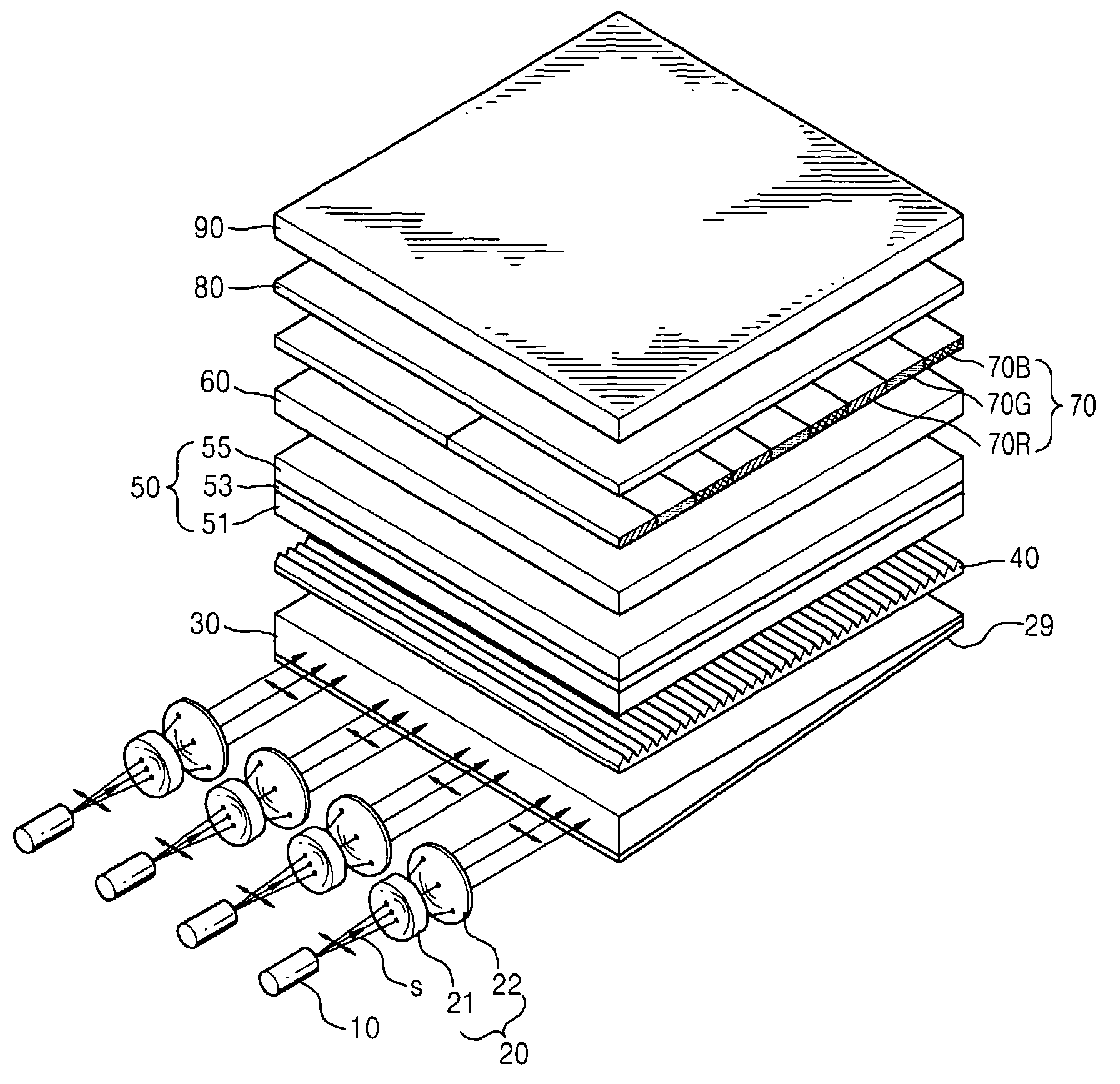
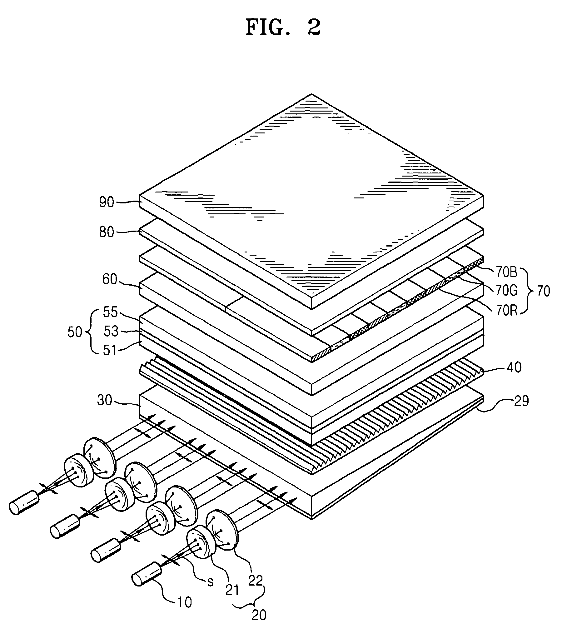
[0019]A photoluminescence LCD of example embodiments will now be described more fully with reference to the accompanying drawings, in which example embodiments are shown. In the drawings, the thicknesses of layers and regions are exaggerated for clarity.

[0020]It will be understood that when an element or layer is referred to as being “on,”“connected to” or “coupled to” another element or layer, it can be directly on, connected or coupled to the other element or layer or intervening elements or layers may be present. In contrast, when an element is referred to as being “directly on,”“directly connected to” or “directly coupled to” another element or layer, there are no intervening elements or layers present. Like numbers refer to like elements throughout. As used herein, the term “and / or” includes any and all combinations of one or more of the associated listed items.

[0021]It will be understood that, although the terms first, second, etc. may be used herein to describe various elemen...


PUM

PropertyMeasurementUnit
wavelength bandaaaaaaaaaa

Abstract

Provided is a photoluminescence liquid crystal display (LCD) using a light source emitting polarized light. The photoluminescence LCD may include a light source emitting polarized light, a light control unit including a liquid crystal layer having a plurality of pixel regions and modulating a polarization direction of the polarized light individually with respect to each of the pixel regions, a polarizer transmitting the modulated light only when the polarized light has a polarization direction, and a photoluminescence layer excited by the light transmitted through the polarizer and emitting excitation light by photoluminescence. Accordingly, an additional polarizer may not be on a rear surface of the light control unit, so that photoluminescence LCD may have a simpler structure and increased light use efficiency.

Description

PRIORITY STATEMENT[0001]This application claims priority under 35 USC §119 to Korean Patent Application No. 10-2006-0083653, filed on Aug. 31, 2006, in the Korean Intellectual Property Office (KIPO), the entire contents of which are incorporated herein by reference.BACKGROUND[0002]1. Field[0003]Example embodiments relate to a photoluminescence liquid crystal display (LCD). Other example embodiments relate to a photoluminescence LCD having a simpler panel structure and an increased efficiency in use of light by employing a light source emitting polarized light.[0004]2. Description of the Related Art[0005]An LCD may include a liquid crystal panel formed by injecting a liquid crystal between two substrates having field generating electrodes. An electrical field may be generated by a predetermined or given voltage applied to the electrodes. The generated electrical field may arrange liquid crystal molecules so that light passes through the arranged molecules. The LCD may display images ...

Claims


Application Information

Patent Timeline
Patent Type & Authority Patents(United States)
IPC IPC(8): G02F1/135G02F1/1335
CPCG02B6/0056G02F1/133617G02F1/1335
Inventor HA, KYOUNG-HOCHOI, BYOUNG-LYONGLEE, JAE-HO
Owner SAMSUNG ELECTRONICS CO LTD
Why Eureka
Try Eureka