Hydraulic backhoe shift mechanism

a backhoe and hydraulic technology, applied in the field of earth-moving vehicles, can solve the problems of complex components of the side-shift backho

Inactive Publication Date: 2010-07-13
BLUE LEAF I P INC
View PDF21 Cites 3 Cited by
  • Summary
  • Abstract
  • Description
  • Claims
  • Application Information

AI Technical Summary

Problems solved by technology

Some of the side-shift backhoes required complex components including hydraulically or manually operated clamps or pins.

Method used


Image

  • Hydraulic backhoe shift mechanism
  • Hydraulic backhoe shift mechanism
  • Hydraulic backhoe shift mechanism

Examples


Embodiment Construction

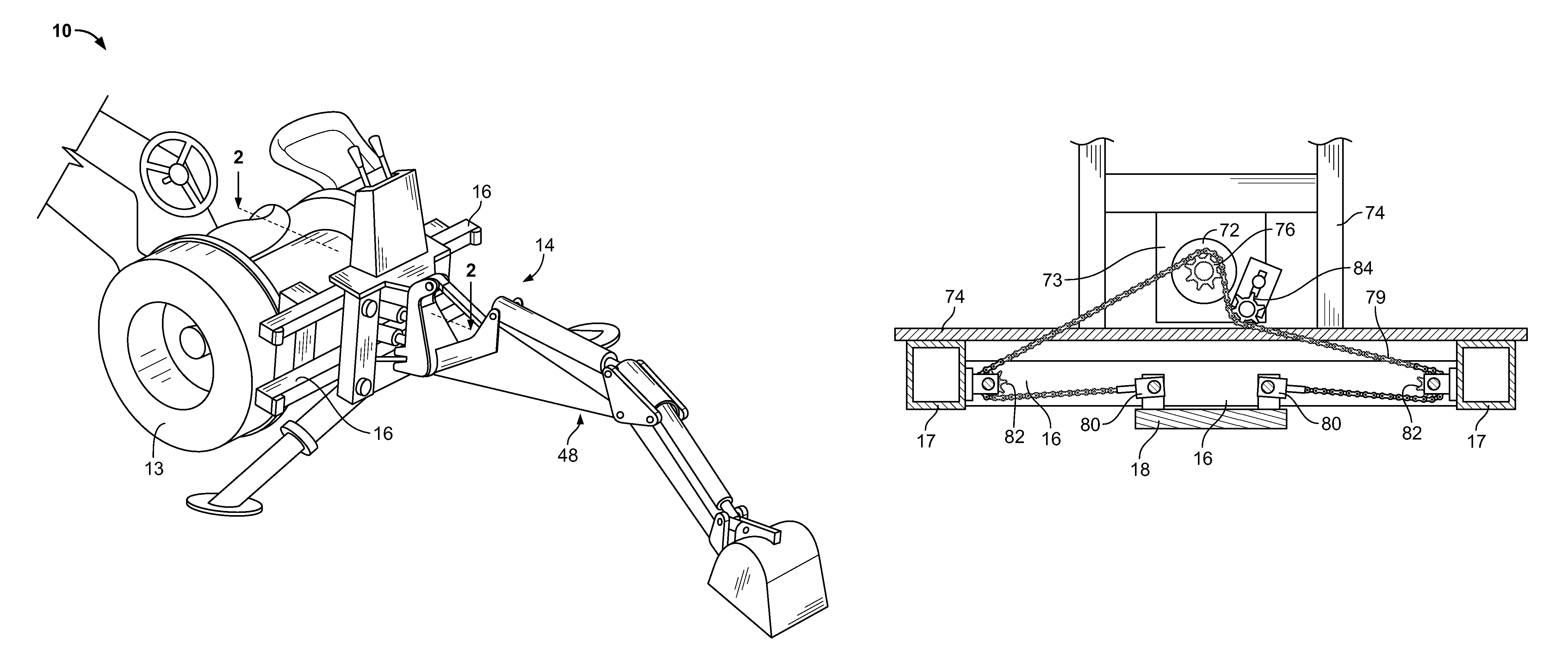
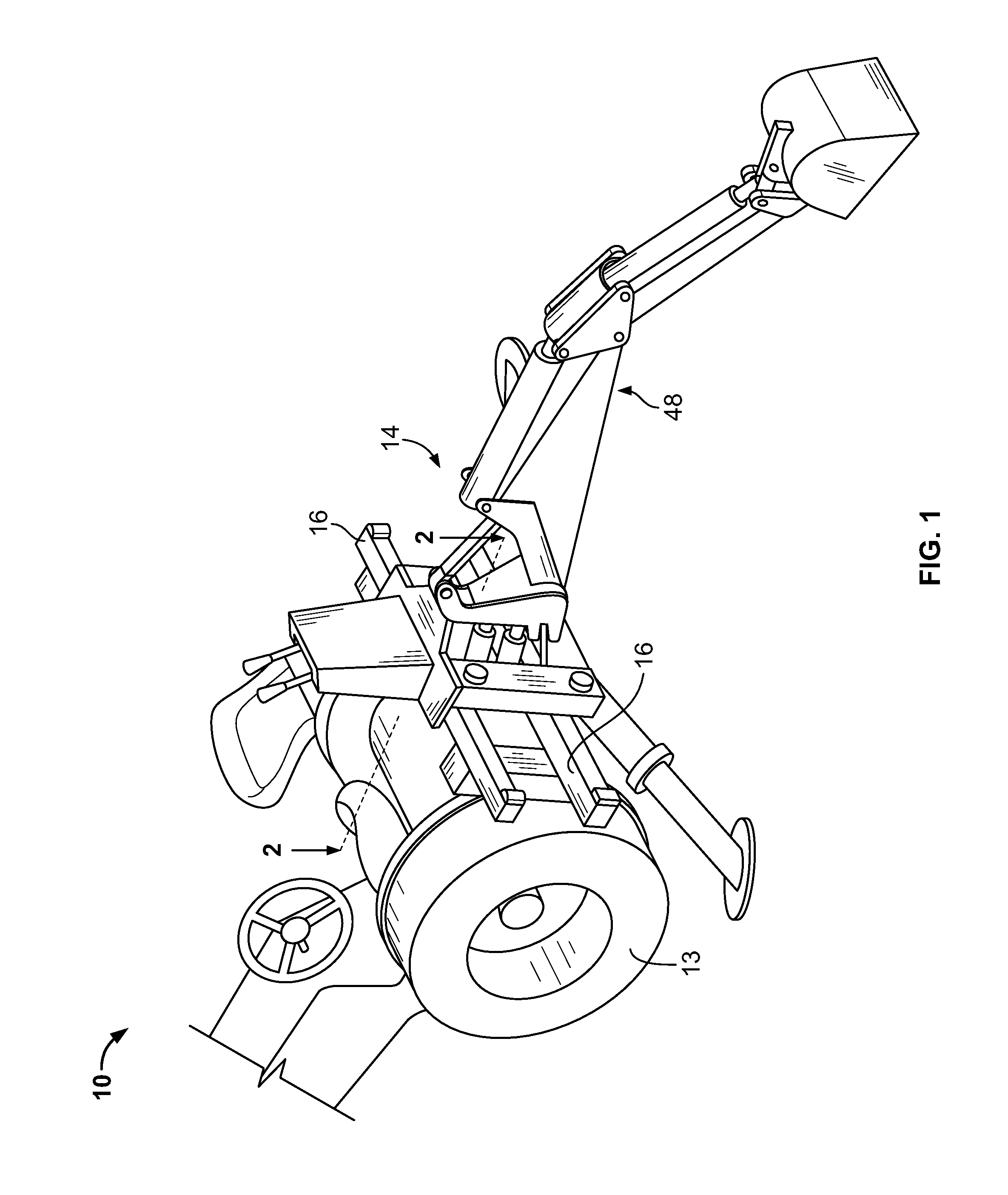
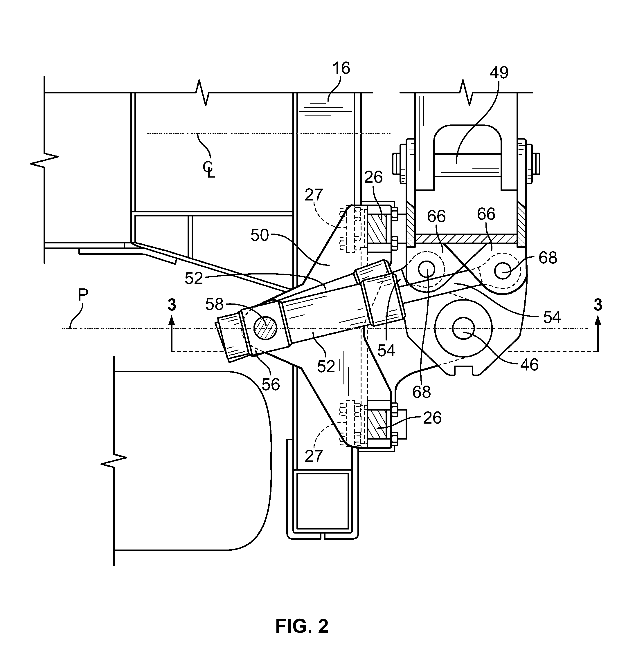
[0015]FIG. 1 of the drawings generally shows an earth-working vehicle 10 including rear wheels 13 with an earth-working implement 14 secured to the rear end of the vehicle 10. The vehicle 10 has a pair of horizontally oriented, vertically spaced rails 16 secured to the rear end of the vehicle 10. Each of the rails 16 is substantially rectangular in cross section (see FIG. 3) and includes a rear vertical implement support plate 18, with the rails releasably connected to vehicle 10 through quick release frame 17. However, other rail and plate arrangements may be used. As most clearly shown in FIG. 3, tower frame 20 consists of upper and lower plates 22 and 24 that are interconnected by a pair of vertical beams 26. The transversely spaced vertical columns or beams 26 each have a pair of lock members or means 28 supported thereon for securely locking the tower frame 20 in any one of a plurality of adjusted positions with respect to rails 16. These lock members or means may be of the typ...


PUM


Abstract

An earth-working vehicle, such as a backhoe loader, has an implement, such as a backhoe, mounted in a manner that the implement can be shifted transversely with respect to the vehicle. A hydraulic motor and roller cable or rack are secured to the vehicle main frame and implement supporting plate to position the implement transversely of the vehicle without the jerky movements of prior backhoe loaders.

Description

FIELD OF THE INVENTION[0001]The present invention is directed to an earth-working vehicle, such as a backhoe loader, having an implement, such as a backhoe, in which the implement is capable of being shifted transversely of the vehicle.BACKGROUND OF THE INVENTION[0002]For many years, it has been common to mount the backhoe support structure or swing tower on a frame and utilize a pair of hydraulic cylinders to pivot the tower with respect to the frame. In such a unit, the hydraulic cylinders are usually connected to the boom support or swing tower on opposite sides of the vertical pivot axis between the swing tower and the frame. For example, in one type disclosed in Long U.S. Pat. No. 3,047,171, the free ends of the piston rods of the hydraulic cylinders are connected to the frame structure at spaced locations while the cylinder barrels are connected at transversely spaced points to the swing tower or mast.[0003]In more recent years, an earth-working vehicle of the type disclosed i...

Claims


Application Information

Patent Timeline
Patent Type & Authority Patents(United States)
IPC IPC(8): E02F5/02
CPCE02F3/386
Inventor JOHNSON, LARRY A.HENNEMANN, MATTHEW J.KATDARE, SUHAS
Owner BLUE LEAF I P INC
Why Eureka
Try Eureka