
Circuit for controlling a double-action hydraulic drive cylinder

Inactive Publication Date: 2010-07-13
BUCHER HYDRAULICS
View PDF5 Cites 10 Cited by
  • Summary
  • Abstract
  • Description
  • Claims
  • Application Information

AI Technical Summary

Benefits of technology

[0012]The invention is based on the task of simplifying the hydraulic circuit while simultaneously achieving a further reduction in the power demand by minimizing the hydraulic flow resistances and thus reducing the degree to which the oil is heated.

Problems solved by technology

A long hydraulic oil line, however, represents a hydraulic resistance, which translates to energy losses and to the heating of the hydraulic oil.
Hydraulically controlled valves and their actuating elements, which also act hydraulically, lead to pressure losses and thus impose a certain power demand.

Method used


Image

  • Circuit for controlling a double-action hydraulic drive cylinder
  • Circuit for controlling a double-action hydraulic drive cylinder
  • Circuit for controlling a double-action hydraulic drive cylinder

Examples


Embodiment Construction

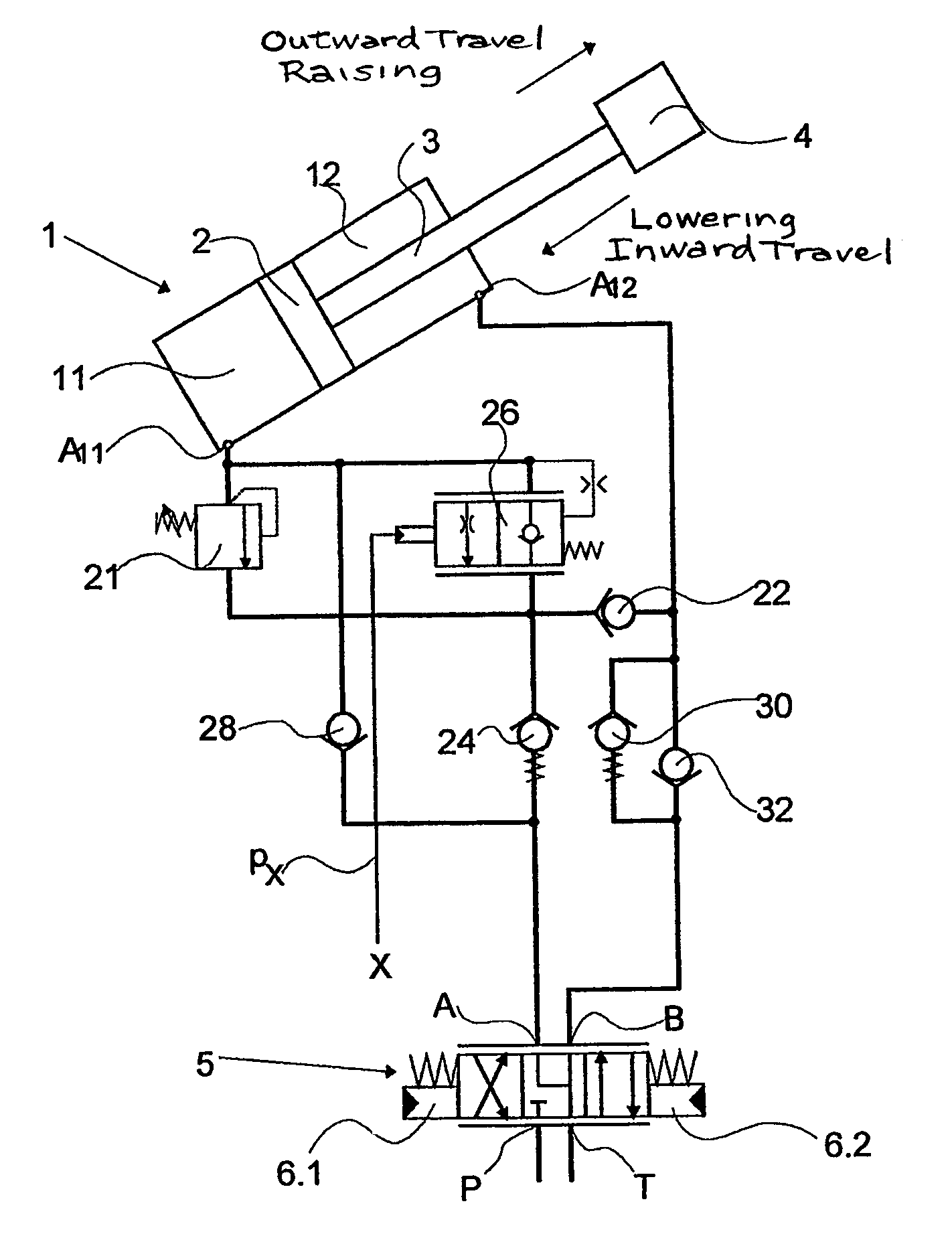
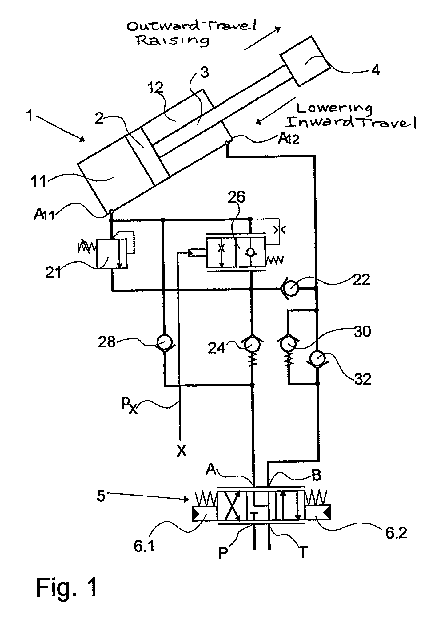
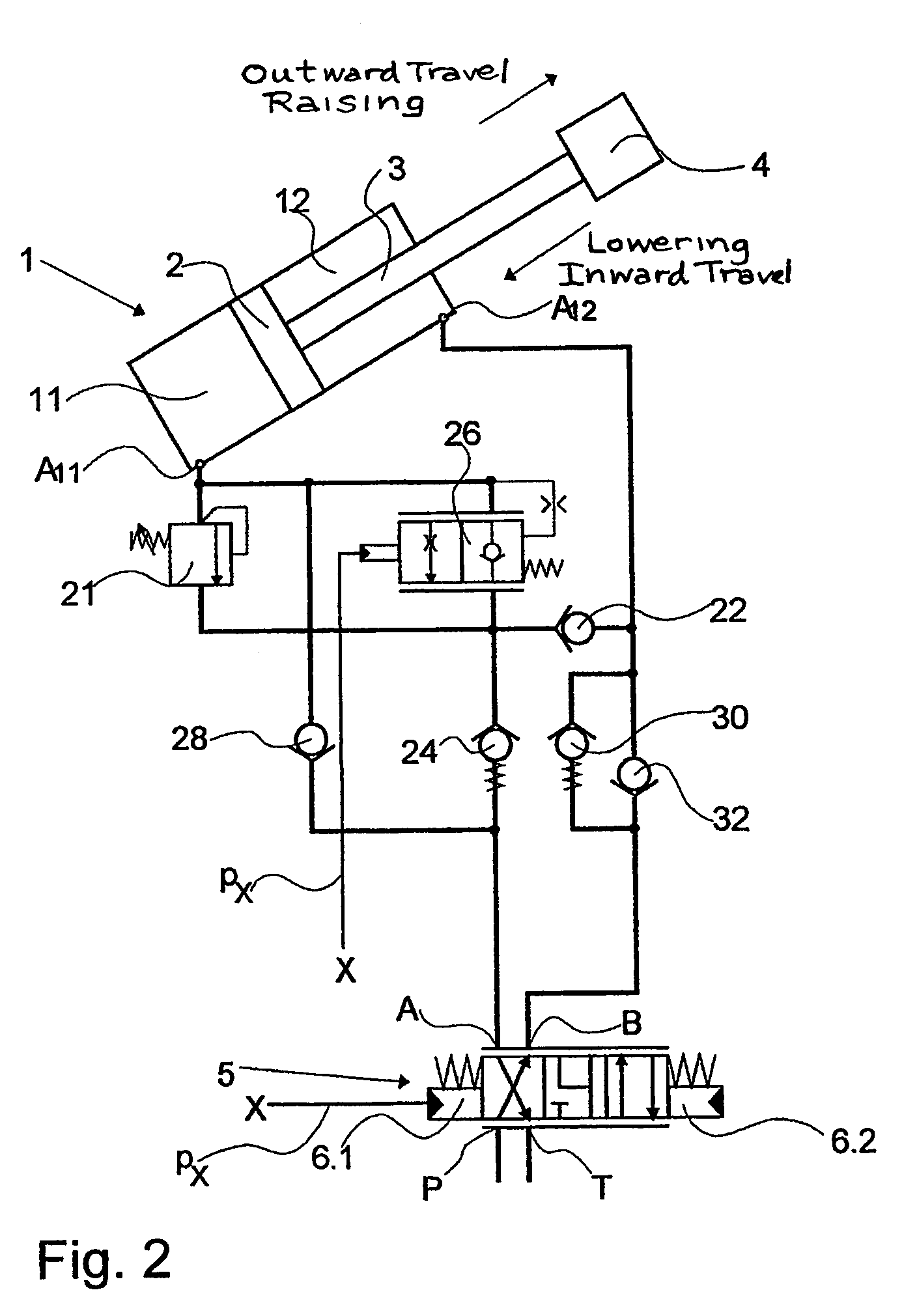
[0020]FIG. 1 shows a double-action hydraulic drive cylinder 1, in which a load 4 can be moved by a piston 2 and a piston rod 3 connected to the piston. The drive cylinder 1 can be controlled by a directional control valve 5, which can be actuated in the known manner by drives 6. The directional control valve 5 has a pump port P in the conventional manner, a tank port T, a first working port A, and a second working port B.

[0021]A first drive 6.1 moves the directional control valve 5 into the position in which the pump port P is connected to the working port B and in which the tank port T is connected to the working port A in the known manner. A second drive 6.2 moves the directional control valve 5 into the position in which the pump port P is connected to the working port A, and in which the tank port T is connected to the working port B. If drive 6 is not actuated, the directional control valve 5 assumes the position shown, which represents the neutral position of the directional c...


PUM


Abstract

Circuit for controlling a double-action hydraulic drive cylinder includes a directional control valve having working ports A and B, a pump port P, and a tank port T, wherein the directional control valve has a neutral position in which pump port P is blocked and working ports A, B are connected to tank port T. A pressure-limiting valve and a controllable load-holding valve are connected to the piston space in parallel, and a regeneration check valve is connected in series between a connection point for the parallel components and the rod space. A first precharge valve is connected between the working port A and the connection point, and a first bypass check valve is connected anti-parallel parallel with the first precharge valve and the load-holding valve. A second precharge valve is connected in series with the directional control valve between the tank port P and the rod space.

Description

CROSS-REFERENCE TO RELATED APPLICATIONS[0001]This is a U.S. national stage of International Application No. PCT / CH2006 / 000057, filed on 27 Jan. 2006. Priority is claimed on Swiss Application No. 1366 / 05, filed on 19 Aug. 2005.BACKGROUND OF THE INVENTION[0002]1. Field of the Invention[0003]The invention pertains to a circuit for controlling a double-action hydraulic drive cylinder having a piston separating a piston space from a rod space, wherein hydraulic oil can be supplied to the piston space while hydraulic oil simultaneously flows out of the rod space, and hydraulic oil can be supplied to the rod space while hydraulic oil simultaneously flows out of the piston space, the cylinder being actuated by a directional control valve having working ports A and B, a pump port P, and a tank port T.[0004]2. Description of the Related Art[0005]Double-action drive cylinders are often used in devices for raising and lowering loads. In the one direction of movement, hydraulic oil is fed into t...

Claims


Application Information

Patent Timeline
IPC IPC(8): F15B11/044F15B11/024
CPCB66F9/22E02F9/2203F15B11/003F15B11/024F15B13/021F15B2211/30505F15B2211/3051F15B2211/30515F15B2211/30525F15B2211/3058F15B2211/3127F15B2211/3144F15B2211/31576F15B2211/31588F15B2211/329F15B2211/351F15B2211/353F15B2211/50518F15B2211/55F15B2211/88F15B11/044
Inventor HRISTOV, IVANZURCHER, JOSEF
Owner BUCHER HYDRAULICS
Learn More