Dynamic barrier system

a barrier system and dynamic technology, applied in the field of barriers, can solve problems such as/or dangerous removal, and achieve the effect of not waste of ammunition

Inactive Publication Date: 2010-07-13
UNITED STATES OF AMERICA THE AS REPRESENTED BY THE SEC OF THE ARMY
View PDF21 Cites 3 Cited by
  • Summary
  • Abstract
  • Description
  • Claims
  • Application Information

AI Technical Summary

Benefits of technology

[0010]Viewed from yet another aspect, our inventive barrier system advantageously deploys munition components only when needed. As a result, barrier areas are not made particularly hazardous until needed, and munitions are not

Problems solved by technology

In this inventive manner, difficult and/or da

Method used


Image

  • Dynamic barrier system
  • Dynamic barrier system
  • Dynamic barrier system

Examples


Embodiment Construction

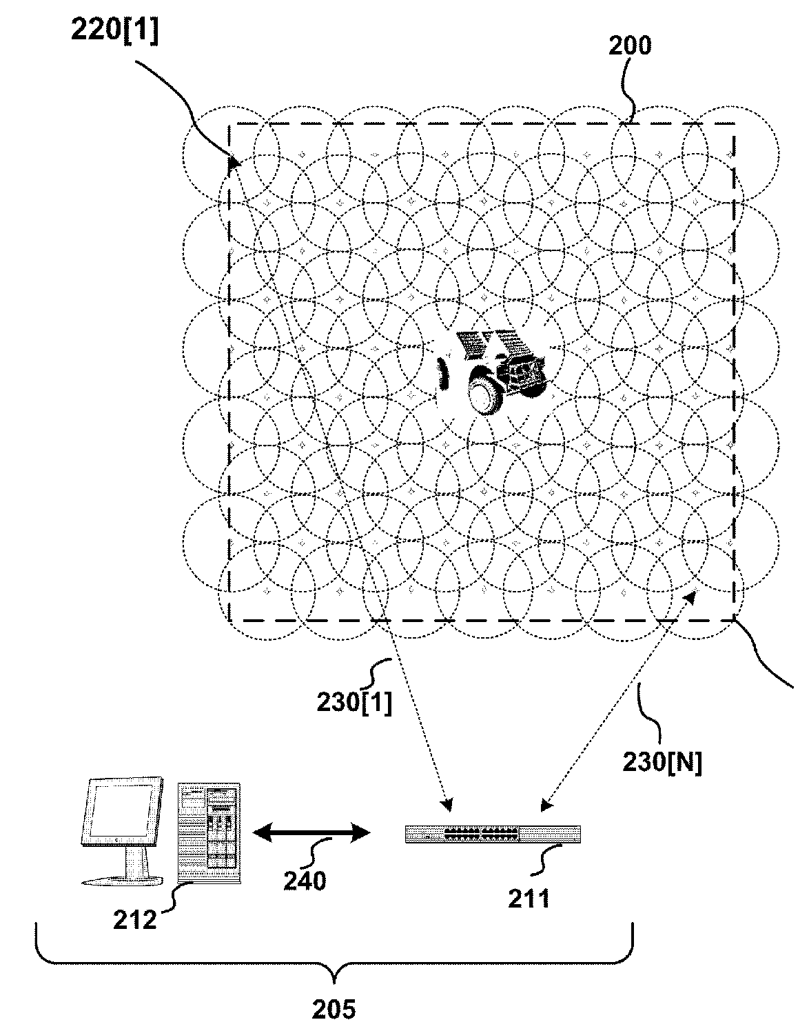
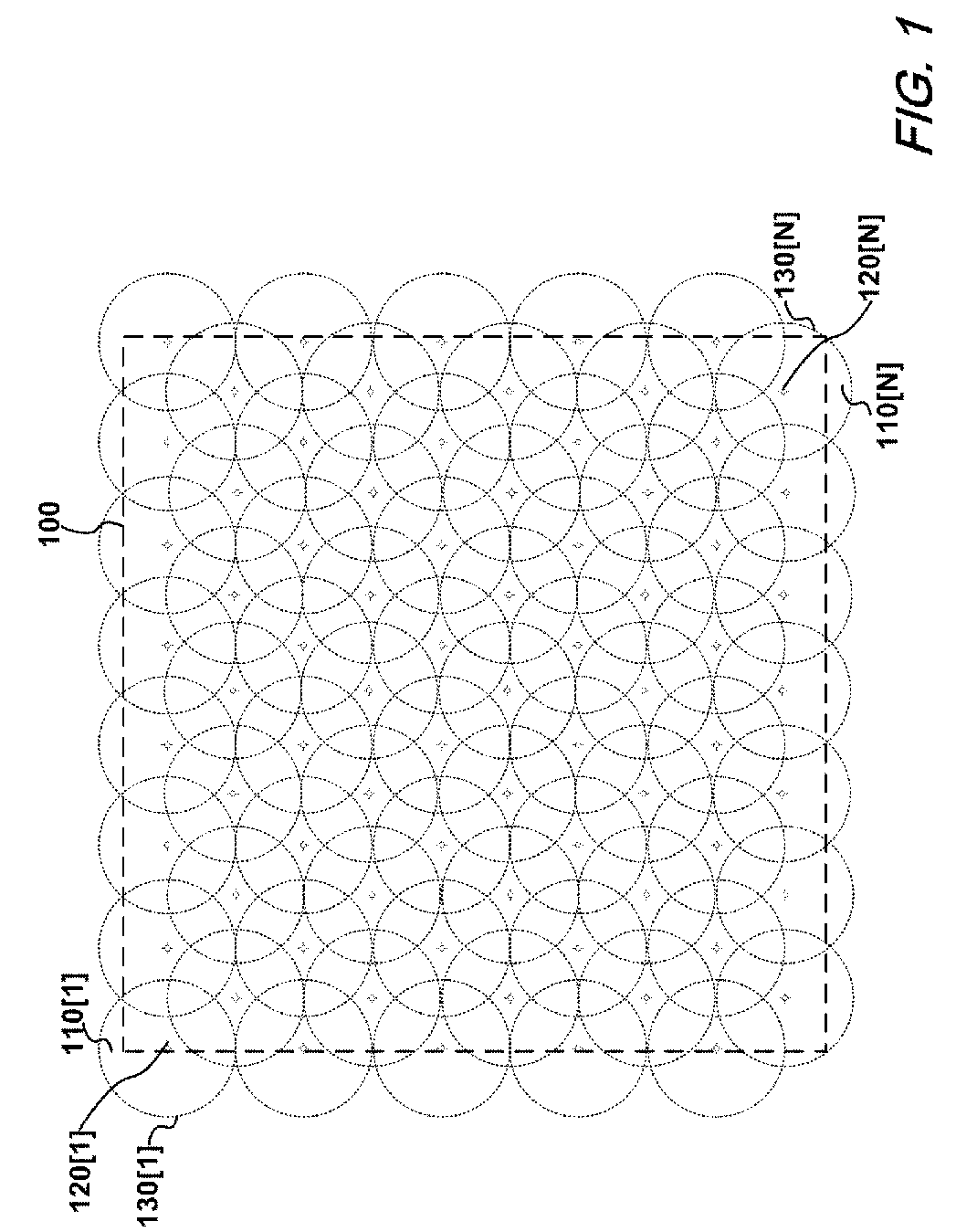
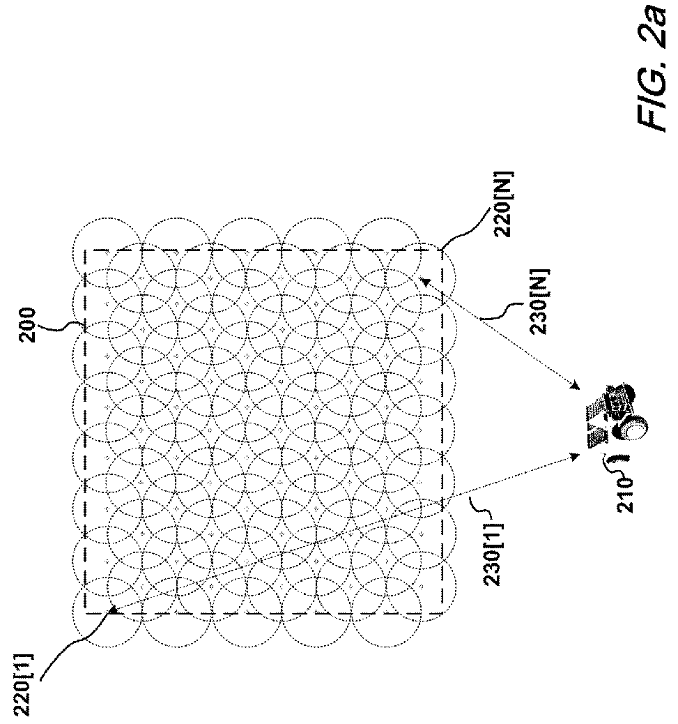
[0020]FIG. 1 is a schematic illustration of a barrier area that will serve as a starting point for a discussion of the present invention. In particular, and with reference to that FIG. 1, there is shown a barrier area 100 having a plurality of barrier sensor systems 120[1] . . . 120[N] situated therein. Each of the individual barrier sensor systems 120[1] . . . 120[N] monitors a respective barrier sensory field 110[1] . . . 110[N], each individual field being defined by a barrier sensory field perimeter 130[1] . . . 130 [N], respectively.

[0021]At this point it is worth noting that the barrier area 100 depicted in FIG. 1 is a particular area over which our inventive barrier system is operating. The barrier sensor systems 120[1] . . . 120[N] deployed within the barrier area 100 each comprise at least one particular type of sensor. Each individual barrier sensory field 110[1] . . . 110[N] may be associated with situational awareness, anti-personnel effects, anti-vehicle effects, or non...


PUM


Abstract

A dynamic barrier system including a number of sensors that monitor a barrier area to determine specific types of objects approaching, within, or exiting the barrier area. Depending upon the type of object(s), the dynamic barrier system initiates an appropriate action, both lethal and non-lethal. The barrier system may advantageously deactivate after its intended period of operation eliminating difficult and/or dangerous removal.

Description

CROSS REFERENCE TO RELATED APPLICATION[0001]This application claims the benefit under 35 USC 119(e) of U.S. Provisional Patent Application No. 60 / 594,239 filed Mar. 15, 2005, the entire file wrapper contents of which provisional application are herein incorporated by reference as though set forth at length.FEDERAL RESEARCH STATEMENT[0002]The invention described herein may be made, used, or licensed by or for the United States Government for government purposes without payment of any royalties thereon or therefore.FIELD OF THE INVENTION[0003]This invention relates generally to the field of barrier systems, and in particular to a dynamic barrier system that monitors an area, senses and determines specific types of objects within that area, and actively / dynamically reacts to those objects.BACKGROUND OF THE INVENTION[0004]For centuries, barrier systems of various types have been employed to impede or prevent the infiltration of undesirables into an area. From the earliest moats and high...

Claims


Application Information

Patent Timeline
IPC IPC(8): B64D1/04
CPCF41H11/00F41H11/06F42B12/201F42B12/365F42B23/00
Inventor HOHIL, MYRONKOKODIS, VICTOR N.MELLINI, MARKPELTZER, BRIANSEBASTO, ANTHONY
Owner UNITED STATES OF AMERICA THE AS REPRESENTED BY THE SEC OF THE ARMY
Why Eureka
Try Eureka