Fluid container closure mechanism with detachable valve assembly

a technology of liquid container and closure mechanism, which is applied in the field of liquid container closure mechanism, can solve the problems of material from the fluid passing through the valve or spout, and accumulating particulate residue in the spaces between the valve's surfaces

Inactive Publication Date: 2010-07-13
HYDRAPAK LLC
View PDF21 Cites 47 Cited by
  • Summary
  • Abstract
  • Description
  • Claims
  • Application Information

AI Technical Summary

Benefits of technology

[0012]The valve body is radially deformable so that the ears may be rotatably advanced onto the inner surface of the guide members thus allowing the valve body to be removed from the sleeve. This is accomplished since the ears may slide along the inner surface of the sleeve, at the location of the guide members, with the ears being disengaged from the slots that normally limit the longitudinal travel of the valve body. To this end, the stop members in the form of above described ears each have a chamfered surface that forms a wedge along one shoulder edge thereof to assist in the advancement of the ears onto the guide members when the valve body is rotated in a counterclockwise direction.
[0013]The fluid discharge or valve assembly also may include a central post that is oriented along the central axis of the sleeve with the valve body being in the form of a cylindrical shell that is positioned in the interior region between the central post and the inner surface of the sleeve. The valve body has a closed outer end that is provided with an aperture. When the valve assembly is in the closed position, the aperture engages the top of the post. However, when the valve assembly is in the open position, the post and aperture are disengaged so that fluid may flow around the central post and out of the aperture. The post may also have support members which face the slots in the sleeve. These support members are in the form of longitudinally extending ribs which resist deformation of the valve body when the ears are engaged in the slots thus resisting removal of the valve body from the sleeve during times when the stop members are positioned in the slots.

Problems solved by technology

Unfortunately, the pop-up valves or spouts which are utilized with such caps are not removable or capable of being disassembled.
This is a significant disadvantage in that material from the fluid passing through the valve or spout, especially sweetened material such as Gatorade or punch, tends to accumulate particulate residue in the spaces between the valve's surfaces.
Moreover, since such valves are often opened utilizing one's teeth, saliva and mucous residue can become lodged in such locations.
Such residual material in the valve or spout can become a health hazard.
In addition, it can also interfere with the proper functioning of the valves or spouts.
Consequently, even though such bottles or containers are reusable due to the removability of the container cap, eventually the pop-up valve or spout becomes difficult or unhealthy to use.

Method used


Image

  • Fluid container closure mechanism with detachable valve assembly
  • Fluid container closure mechanism with detachable valve assembly
  • Fluid container closure mechanism with detachable valve assembly

Examples


Embodiment Construction

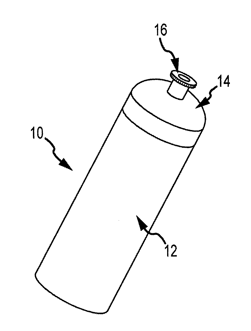
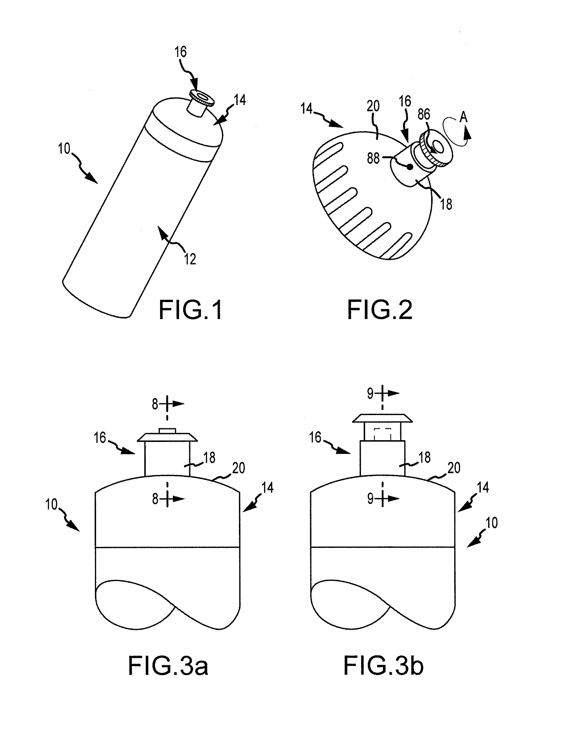
[0029]Referring first to FIG. 1, a fluid container 10 is illustrated and preferably includes a receptacle portion 12, which is designed to house or retain fluid such as water, and a cap portion 14, which is preferably removably secured to the receptacle portion 12. A reclosable pop-up type fluid discharge or valve assembly 16 is preferably incorporated centrally in the top of the cap portion 14 and forms a spout for container 10. It should be understood, however, that the reclosable valve assembly 16 of the present invention may be utilized with any type of fluid container arrangement or structure, and that the cap portion 14 may also be integral with the receptacle portion 12.

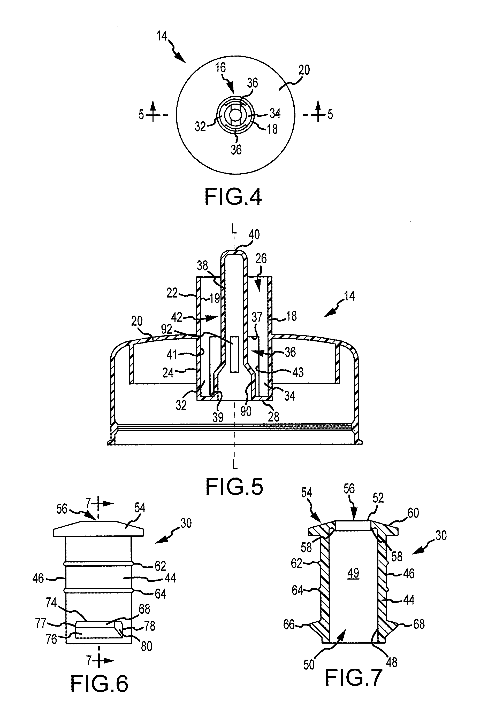
[0030]While the concept of a pop-up valve or spout for a liquid container is not new, existing valve structures accumulate dirt and residue between the pressure sealing surfaces of the movable valve body. This is due to the fact that while the entire spout assembly or cap may be removable from the container fo...


PUM


Abstract

A fluid container is disclosed. The container includes an enclosure for containing liquid and a first closure member. The first closure member is in the form of a fluid discharge assembly which includes a selectively removable valve body mounted for movement between an open position to permit flow of liquid from the enclosure and a closed position to prevent flow of liquid through the fluid discharge assembly. In addition, the closure includes a cap member mountable to a container, and the cap member defines a product outlet passage. The valve body is disposed for movement within the outlet passage between an open position to permit flow of product through the passage from said container and a closed position to prevent flow of product through the passage. The valve body is selectively removable from the outlet passage.

Description

FIELD OF THE INVENTION[0001]The present invention relates generally to fluid containers and, more particularly, to closure mechanisms for drinking bottles such as sports and water bottles. Specifically, the present invention relates to pop-up type valve assemblies for fluid container closure mechanisms.DESCRIPTION OF THE PRIOR ART[0002]Refillable plastic drinking bottles and containers with removable tops have been used for many years for conveniently storing and transporting beverages. Numerous closure caps have been developed for such beverage containers to facilitate ease of delivery of the container's contents without spillage utilizing, by way of example, one-way valves, positive closure valves, and devices which act as a seal and closure valve. Sports bottles are one type of such container which are convenient, reusable, flexible plastic drinking bottles with screw-on or snap-on tops. Such bottles are typically provided with either a flexible plastic drinking straw that extend...

Claims


Application Information

Patent Timeline
Patent Type & Authority Patents(United States)
IPC IPC(8): B67B1/00
CPCB65D47/243
Inventor HEIBERGER, ROBERT A.
Owner HYDRAPAK LLC
Why Eureka
Try Eureka