Backlight unit for test device of LCD panel
a backlight unit and test device technology, applied in semiconductor devices, lighting and heating apparatus, instruments, etc., can solve the problems of increasing the cost of operating the tester, reducing the lifetime of the lamp, etc., and achieve the effect of preventing brightness deviation and increasing the lifetime of the backlight uni
- Summary
- Abstract
- Description
- Claims
- Application Information
AI Technical Summary
Benefits of technology
Problems solved by technology
Method used
Image
Examples
first embodiment
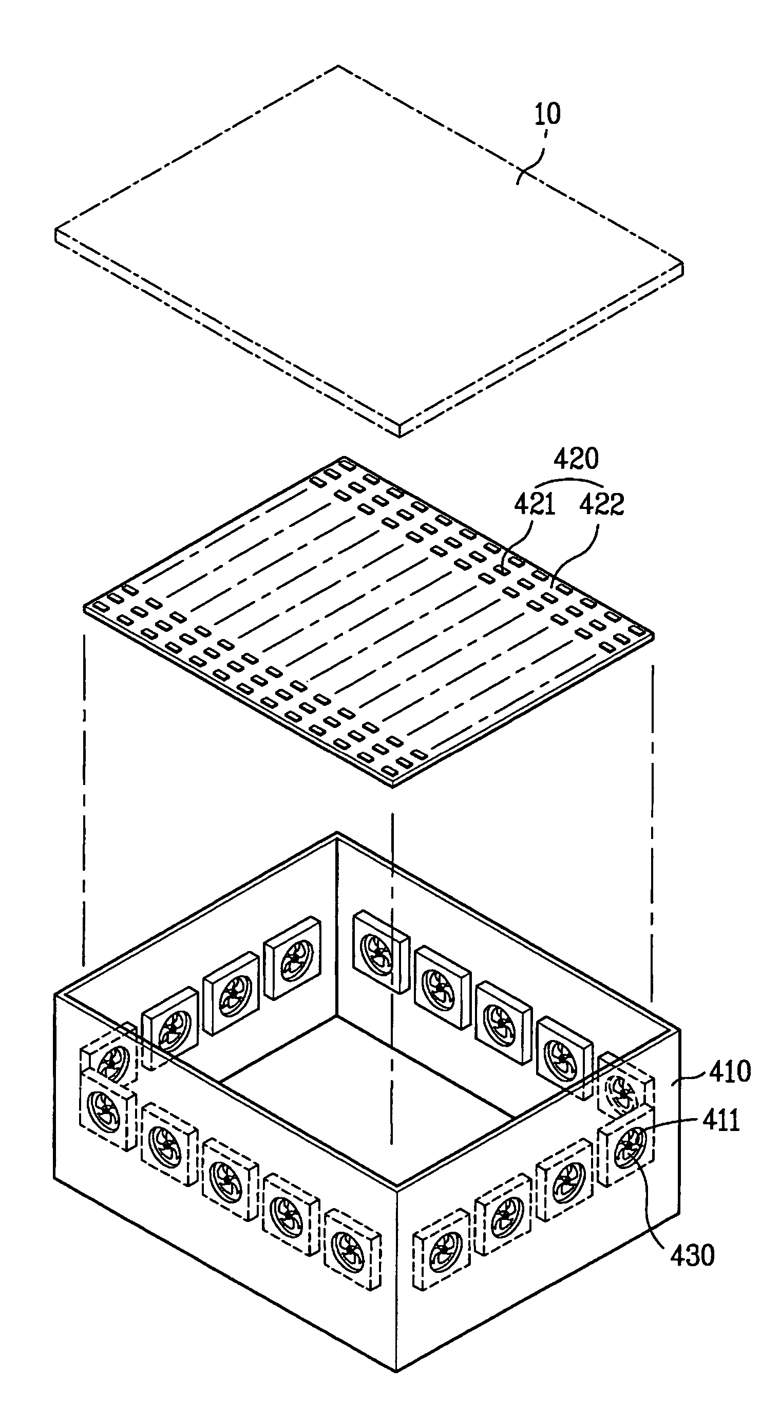
[0042]FIGS. 3 and 4 are an exploded perspective view and a side sectional view illustrating a backlight unit for a test device of an LCD panel according to the present invention.
[0043]As shown in FIGS. 3 and 4, the backlight unit for a test device of an LCD panel according to the first embodiment of the present invention includes a chamber 410, a backlight 420, and a plurality of circulating fans 430.
[0044]The chamber 410 has a rectangular box shape having a predetermined volume therein, with an open top surface. The chamber 410 is provided with a plurality of through holes 411 along the perimeter of the chamber 410. An inner space of the chamber 410 communicates with its outer space through the through holes 411.
[0045]The through holes 411 may be formed along the entire of the perimeter of the chamber 410, along two opposing portions of the perimeter, or along one portion of the perimeter.
[0046]Alternatively, the chamber 410 may have a cylindrical shape or a polygonal box shape hav...
second embodiment
[0064]FIGS. 5 and 6 illustrate a backlight unit according to the present invention.
[0065]As shown in FIGS. 5 and 6, the backlight unit according to the second embodiment of the present invention includes a chamber 410, a backlight 420, circulating fans 430, and a heat-radiating member 440.
[0066]The second embodiment of the present invention differs from the first embodiment in that a heat-radiating member 440 is further provided in the backlight unit.
[0067]The cooling effect of air circulating on the PCB substrate 422 is increased when air from outside the chamber 410, which is vented into the chamber 410, makes effective contact with the PCB substrate 422. In the second embodiment of the present invention, the heat-radiating member 440 is used to increase the effective contact area between the circulated air and the PCB substrate 422.
[0068]Hereinafter, the construction of the second embodiment is described in detail.
[0069]The chamber 410, the backlight unit 420 and the circulating ...
third embodiment
[0082]FIGS. 7 and 8 illustrate a backlight unit according to the present invention.
[0083]As shown in FIGS. 7 and 8, the backlight unit according to the third embodiment of the present invention includes a chamber 410, a backlight 420, and a refrigerant pipe 450.
[0084]In the third embodiment of the present invention, the refrigerant pipe 450 is provided inside the chamber 410 to facilitate cooling of the inside of the chamber 410 of the backlight unit. The refrigerant pipe 450 is designed such that a low temperature refrigerant flows therein.
[0085]In other words, the third embodiment of the present invention provides a reduced temperature inside the chamber 410 due to the flow of refrigerant of a low temperature within the refrigerant pipe 450.
[0086]Hereinafter, the third embodiment of the invention will be described in more detail.
[0087]The chamber 410 and the backlight unit 420 of the backlight unit according to the third embodiment of the present invention are the same as those of...
PUM
 Abstract
Description
Claims
Application Information
 - R&D
- Intellectual Property
- Life Sciences
- Materials
- Tech Scout
- Unparalleled Data Quality
- Higher Quality Content
- 60% Fewer Hallucinations
Browse by: Latest US Patents, China's latest patents, Technical Efficacy Thesaurus, Application Domain, Technology Topic, Popular Technical Reports.
© 2025 PatSnap. All rights reserved.Legal|Privacy policy|Modern Slavery Act Transparency Statement|Sitemap|About US| Contact US: help@patsnap.com


