
Pick up cap for use with socket connector having plug covering opening

a socket connector and socket technology, applied in the direction of coupling device connection, manufacturing tools, metal working apparatus, etc., can solve the problems of contaminated socket connectors, high-end computers, and extremely unfavorable socket connectors for workstations or servers

Inactive Publication Date: 2010-07-13
HON HAI PRECISION IND CO LTD
View PDF10 Cites 9 Cited by
  • Summary
  • Abstract
  • Description
  • Claims
  • Application Information

AI Technical Summary

Benefits of technology

The invention is a new type of socket connector that prevents particles in air from contaminating the contact terminals in the connector. This is achieved by adding a pick up cap with raised portions that can be held by a user and a pair of shields that cover the seams on the insulative housing. The method involves aligning the guiding recesses on the pick up cap with the guiding posts on the insulative housing, holding the raised portions on the plateau, and attaching the shields to the raised portions. This invention helps to keep the contact terminals clean and prevents any damage during the packaging process.

Problems solved by technology

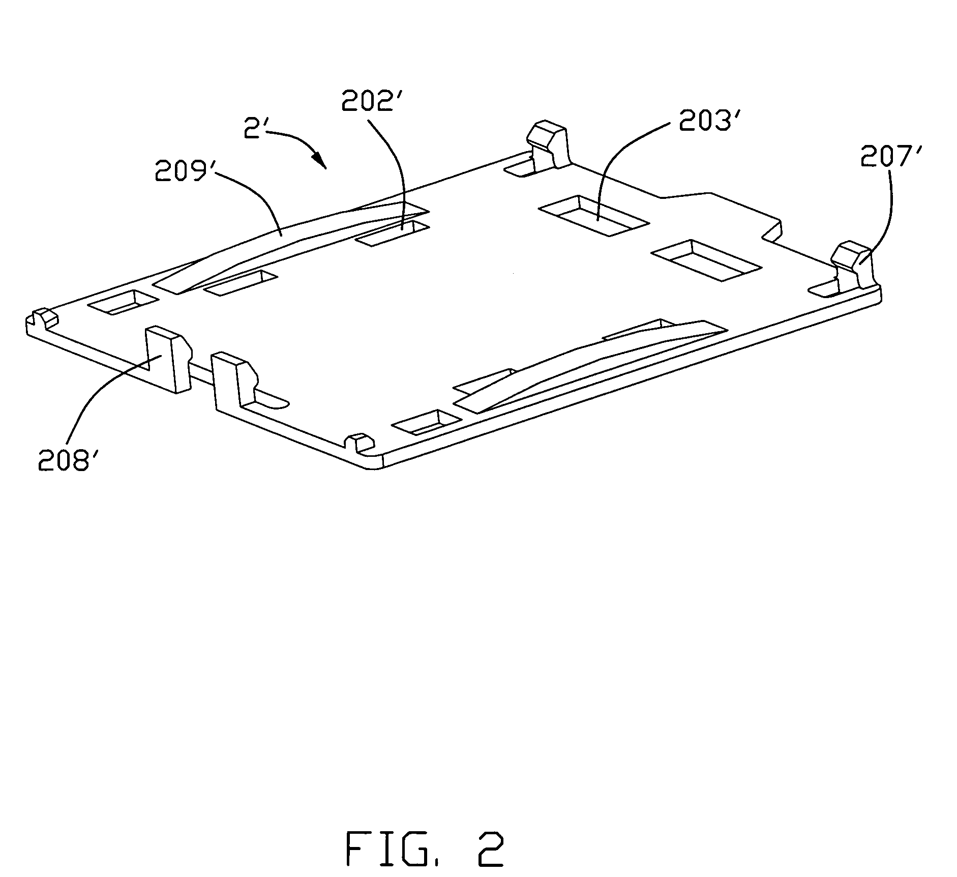
Unfortunately, there is a possibility that the seams 314′ are likely to offer a path to make contact terminals of the socket connector 1′ be contaminated by particles in air or the like.
Once the contact is contaminated, it is very much likely that a reliability or open circuit issue may be raised.
In the worst scenario, the whole system with contaminated socket connector will be malfunctioned.
Such contaminated circumstance in a socket connector is extremely unfavorable to high-end computers systems, for example workstations or servers.

Method used


Image

  • Pick up cap for use with socket connector having plug covering opening
  • Pick up cap for use with socket connector having plug covering opening
  • Pick up cap for use with socket connector having plug covering opening

Examples


Embodiment Construction

[0020]The present invention will be discussed hereinafter in detail in terms of preferred embodiments of the present invention with reference to the accompanying drawings. In the following description, numerous specific details are set forth in order to provide a thorough understanding of the present invention. It will be obvious, however, to those skilled in the art that the present invention may be practiced without these specific details. In other instance, well-known structures are not shown in detail in order to avoid unnecessarily obscure the present invention.

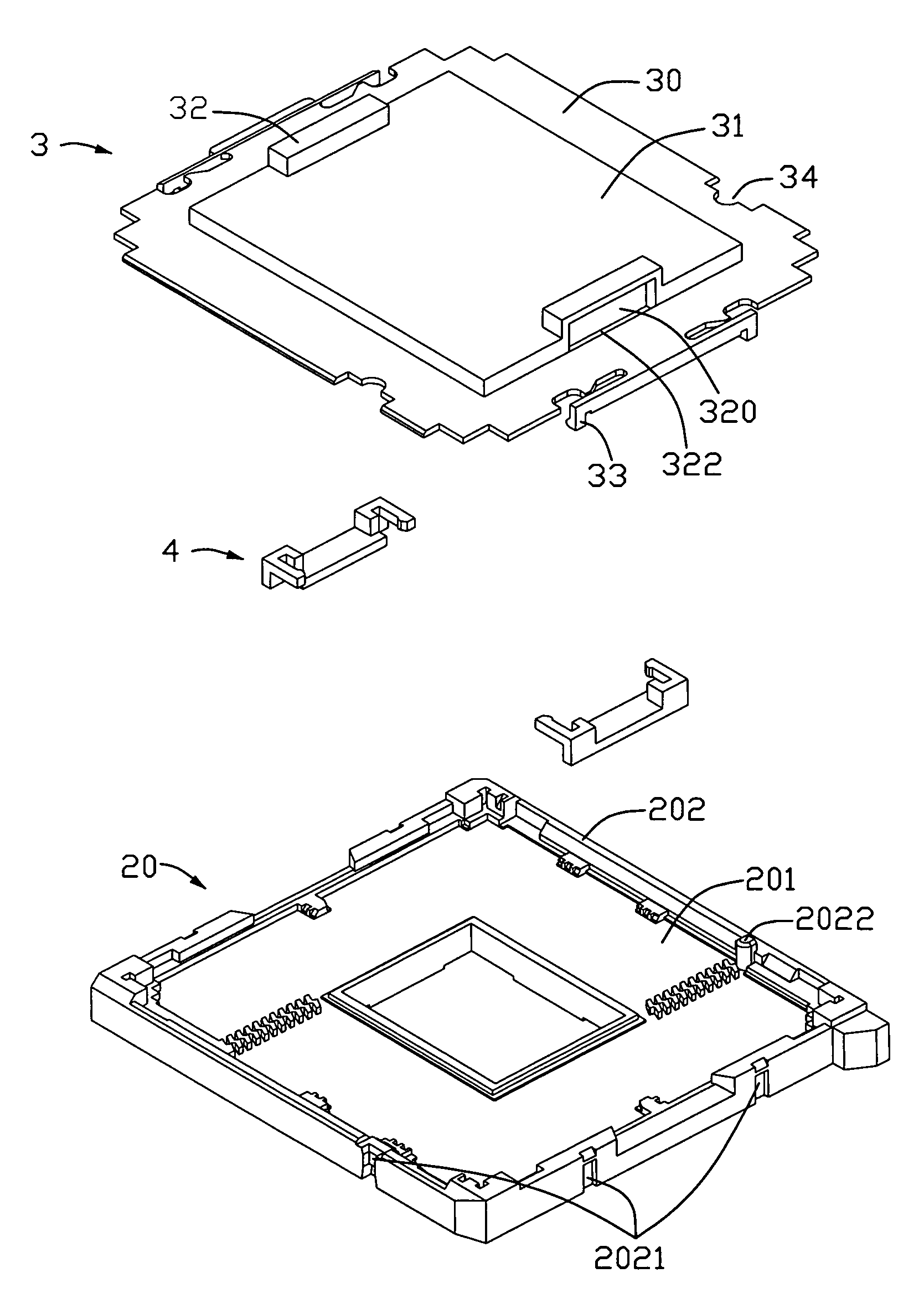
[0021]FIG. 4 is an illustration of exploded view of a socket connector in accordance with the preferred embodiment of the present invention. The socket connector comprises an insulative housing 20 having a base 201 and perimeter sidewalls 202 to cooperatively define an inner cavity. Besides that, the socket connector further comprises a pick up cap 3 and a pair of shield 4. The pick up cap comprises a base plate 30 and a...


PUM

PropertyMeasurementUnit
perimeteraaaaaaaaaa
heat dissipationaaaaaaaaaa
timeaaaaaaaaaa

Abstract

A socket connector has a pick up cap (3) cooperated with lateral shields (4) is provided. The pick up cap (3) has a base plate (30) and a plateau (31) surrounded by the base plate (30). The main purpose of the lateral shields is used for covering seams both on a base plate (30) and under raised portions (32) on opposite sidewalls of the plateau (31). As soon as the seams are covered by the lateral shields (4), paths of particles in air possibly contaminating a plurality of contact terminals restrained in passageways of an insulative housing are able to effectively blocked. Therefore, problems either about reliability or circuit open caused by contaminated socket connector is successfully solved.

Description

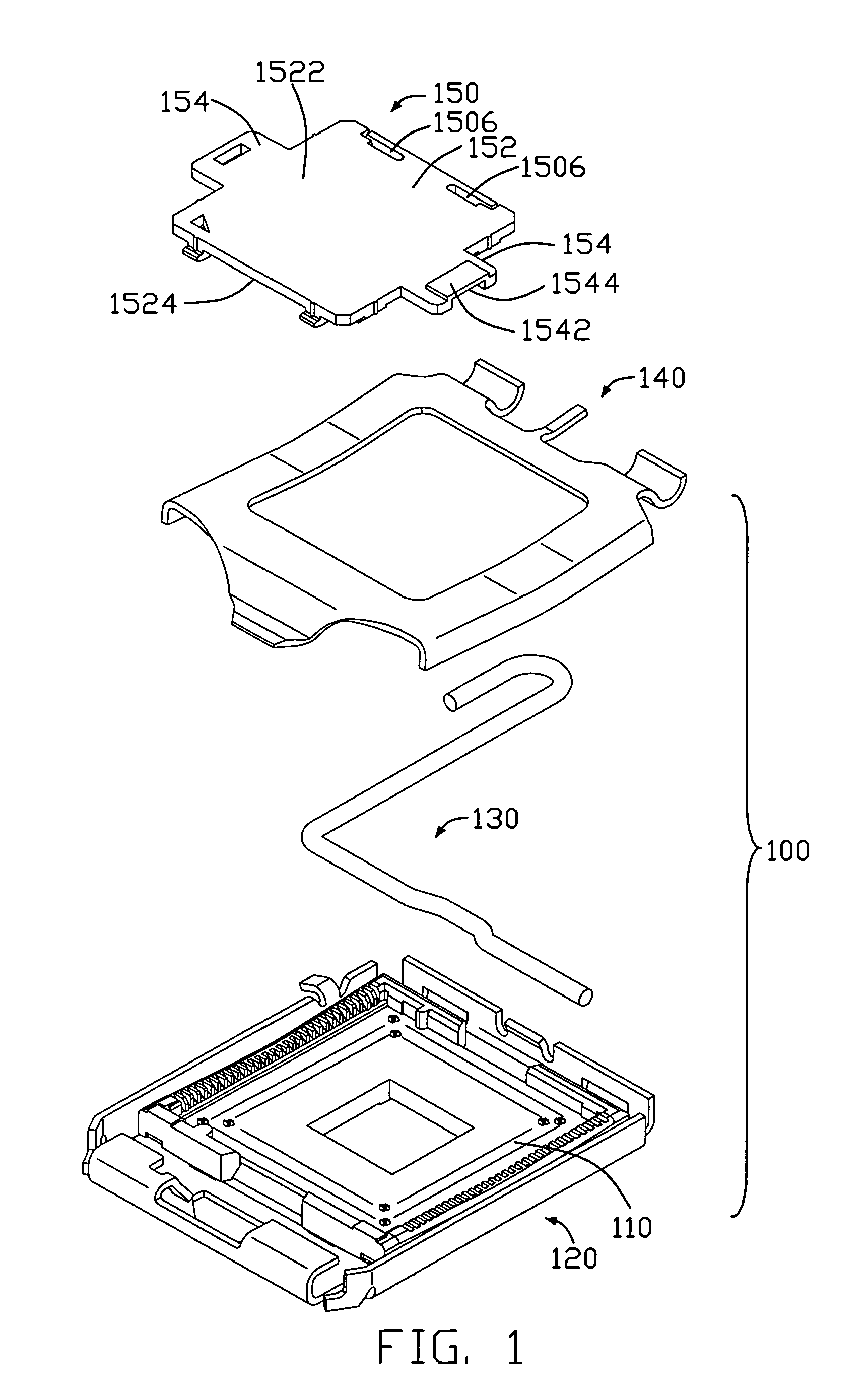
BACKGROUND OF THE INVENTION[0001]1. Field of the Invention[0002]The present invention generally relates to a pick up cap, and more particularly to a pick up cap for use with a socket connector having lateral shields for preventing contact terminals inside the socket connector from being contaminated, for example particles in air.[0003]2. Description of Related Art[0004]Electronic components, such as CPU sockets, are often appropriately positioned on an underlying printed circuit board (PCB) by means of a vacuum suction device. Since the insulative housing of the CPU socket has either a plurality of through holes or a plurality of contact terminals in substantial entire surface thereof, a pick up cap is attached thereon and the vacuum suction device is manipulated on a top flat surface of the pick up cap so as to properly position the CPU socket onto the PCB. Such pick up caps are disclosed in U.S. Pat. No. 7,004,768. Refer to FIG. 1, a CPU socket connector 100, configured by insulat...

Claims


Application Information

Patent Timeline
Patent Type & Authority Patents(United States)
IPC IPC(8): H01R13/44H01R12/71
CPCH01R13/6595H01R43/205Y10T29/53209H01R12/88
Inventor FAN, CHIA-WEI
Owner HON HAI PRECISION IND CO LTD
Learn More