
Methods and systems of tagging objects and reading tags coupled to objects

a technology of object tagging and reading tags, applied in the field of radio frequency identification (rfid) tags, can solve the problems of blocking the ability of a tag reader to read the rfid tag, slow adoption of rfid tags by cattle industry,

Inactive Publication Date: 2010-07-13
ROUND ROCK RES LLC
View PDF27 Cites 5 Cited by
  • Summary
  • Abstract
  • Description
  • Claims
  • Application Information

AI Technical Summary

Benefits of technology

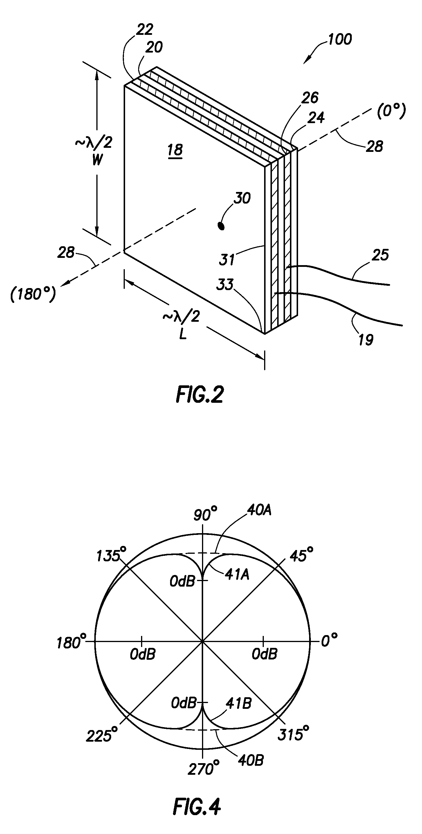
The dual-sided patch antenna maintains effective communication with RFID readers even when proximate to metallic objects or bodies, enhancing reading reliability and accuracy.

Problems solved by technology

However, many industries have been slow to adopt the use RFID tags.
For example, the cattle industry has been slow to adopt RFID tags as a means to identify particular animals because of difficulties in reading the RFID tags.
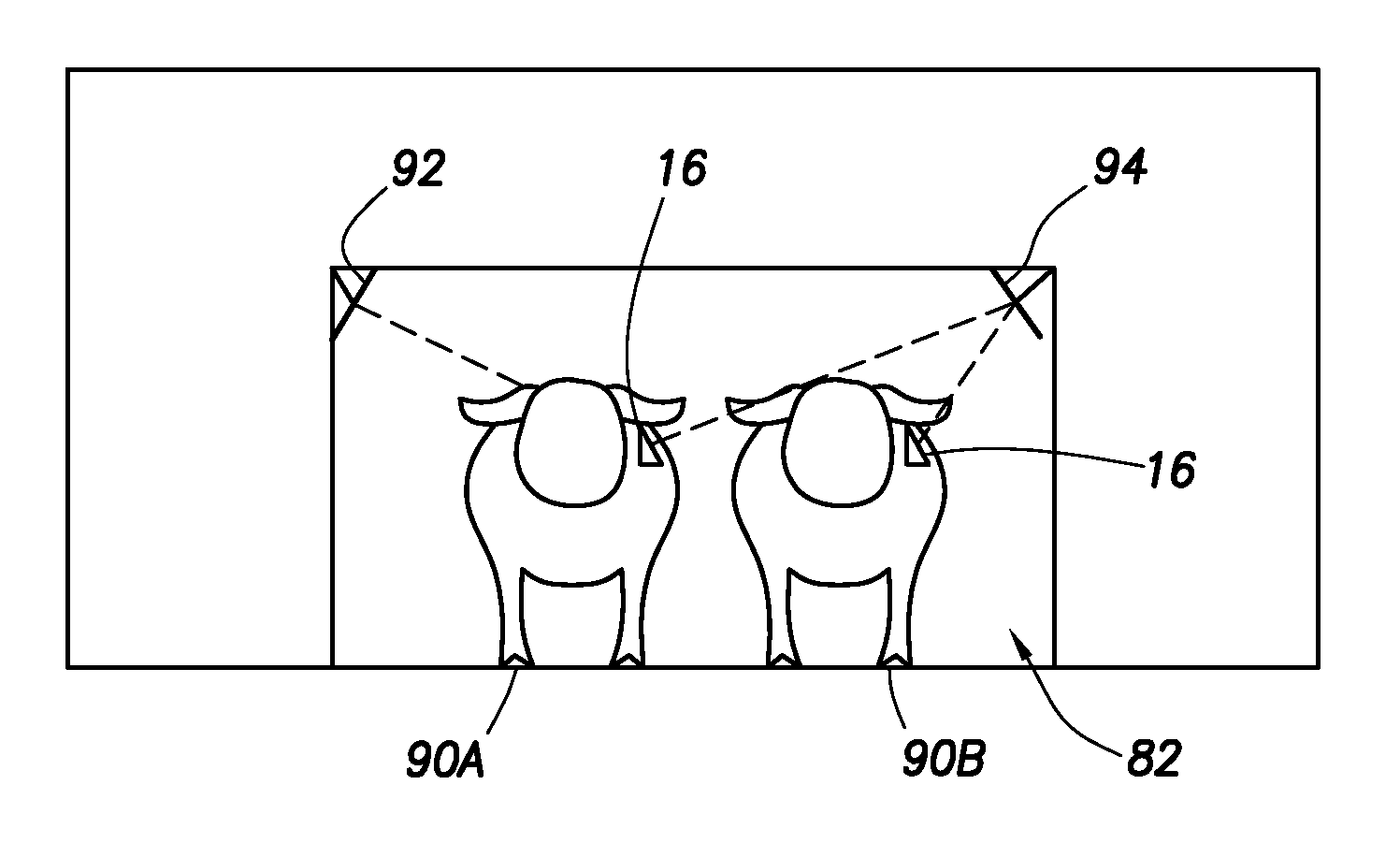
In particular, depending on the physical placement of the RFID tag, the body of the animal may block the ability of a tag reader to read the RFID tag.
Moreover, placing the antenna (e.g., loop or dipole antenna) of an RFID tag close to the body of the animal adversely affects the ability of the antenna to receive power, and also adversely affects the tag's ability to radiate power (for active tags) or reflect power (for passive tags).

Method used


Image

  • Methods and systems of tagging objects and reading tags coupled to objects
  • Methods and systems of tagging objects and reading tags coupled to objects
  • Methods and systems of tagging objects and reading tags coupled to objects

Examples


Embodiment Construction

[0021]The various embodiments disclosed herein are discussed in the context of radio frequency identification (RFID) tags; however, the systems and methods discussed herein have application beyond RFID tags to other types of radio frequency technologies. The discussion of any embodiment in relation to RFID tags is meant only to be illustrative of that embodiment, and not intended to intimate that the scope of the disclosure, including the claims, is limited to that embodiment.

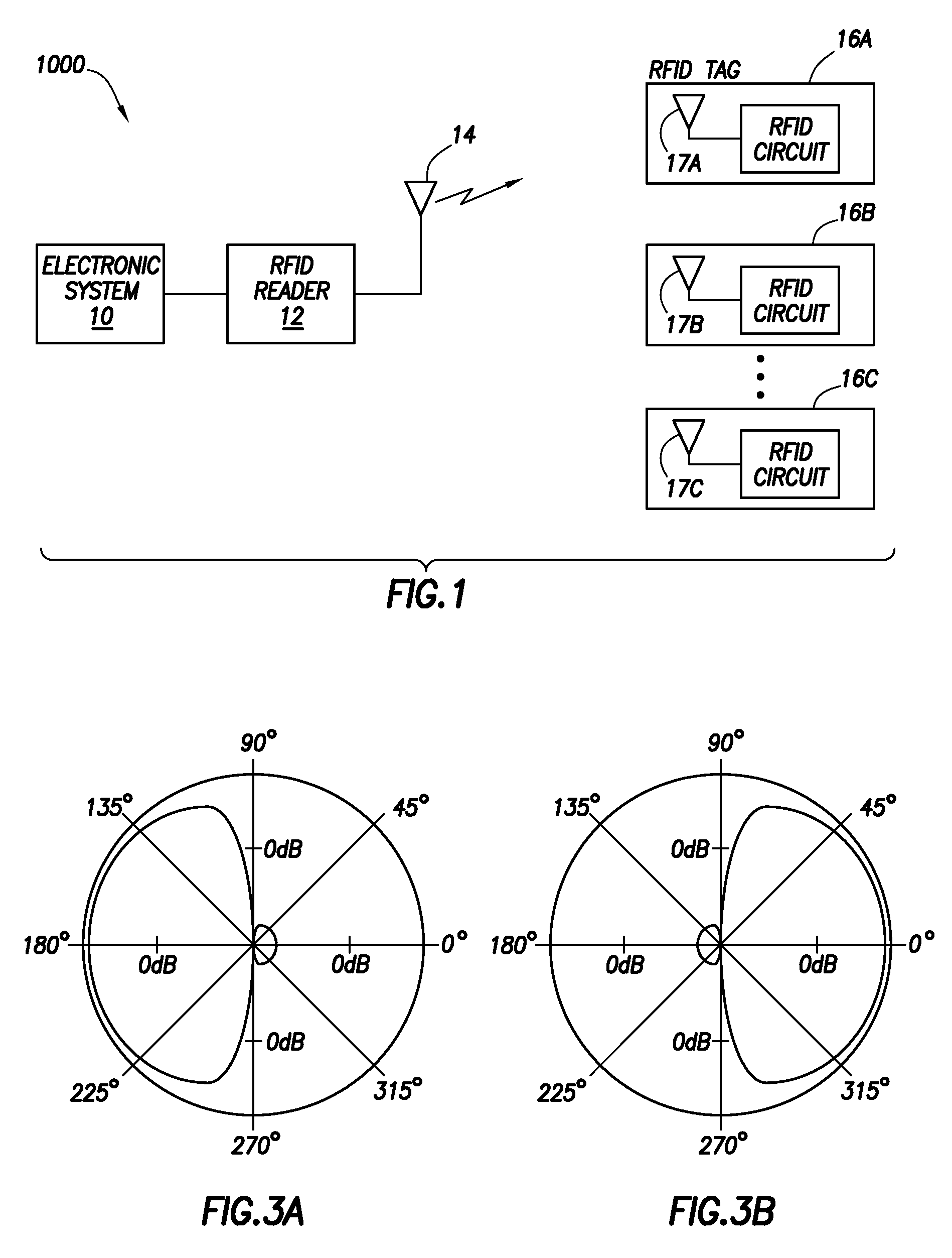
[0022]FIG. 1 illustrates a system 1000 in accordance with at least some embodiments. In particular, system 1000 comprises an electronic system 10 coupled to a RFID reader 12. In some embodiments, electronic system 10 comprises a computer system. By way of antenna 14, the RFID reader 12 communicates with one or more RFID tags 16A-16C (each having antenna 17A-17C as shown) proximate to the RFID reader (i.e., within communication range). The RFID reader 12 may be equivalently referred as an interrogator. The RFID ...


PUM


Abstract

Methods and systems of tagging objects and reading tags coupled to objects. At least some of the illustrative embodiments are systems comprising a reading antenna, a tag reader coupled to the reading antenna, and a radio frequency identification (RFID) tag comprising a tag antenna electromagnetically coupled to the reading antenna. The RFID tag couples to an object such as the body of a living organism or a metallic article. Moreover, the tag antenna has a far-field radiation pattern in a direction away from the object that is substantially unaffected by proximity of the RFID tag to the object, and substantially unaffected by which surface of the RFID tag faces the object.

Description

BACKGROUND[0001]1. Field[0002]The various embodiments are directed to radio frequency identification (RFID) tags for use with metallic articles and / or bodies of living organism, and systems for reading RFID tags.[0003]2. Description of the Related Art[0004]Radio frequency identification (RFID) tags are used in a variety of applications, such as goods identification in wholesale and retail sales, access cards (e.g., building access, garage access), and badging and identification of employees. However, many industries have been slow to adopt the use RFID tags. For example, the cattle industry has been slow to adopt RFID tags as a means to identify particular animals because of difficulties in reading the RFID tags. In particular, depending on the physical placement of the RFID tag, the body of the animal may block the ability of a tag reader to read the RFID tag. Moreover, placing the antenna (e.g., loop or dipole antenna) of an RFID tag close to the body of the animal adversely affec...

Claims


Application Information

Patent Timeline
Patent Type & Authority Patents(United States)
IPC IPC(8): G08B13/14
CPCG06K19/07749G06K7/10009H04B5/0062H04B5/77
Inventor TUTTLE, JOHN R
Owner ROUND ROCK RES LLC
Learn More