Lens design method and radiation source substrate

a radiation source and design method technology, applied in the direction of antenna details, electrical equipment, structural forms of radiation elements, etc., can solve the problems of large bulky, heavy and often expensive, and limited scanning range, and achieve the effect of wide bandwidth

Active Publication Date: 2019-02-05
BAE SYSTEMS PLC
View PDF14 Cites 0 Cited by
  • Summary
  • Abstract
  • Description
  • Claims
  • Application Information

AI Technical Summary

Benefits of technology

[0018]Spiral antennas are widely used in airborne and satellite borne applications such as communications, broadcasting, navigation, remote sensing and globe system positioning due to the wide bandwidth and circular polarization properties of the antenna, which avoid the Faraday rotation effect when radio wave propagates through the ionosphere. In one particular configuration, as illustrated in FIG. 1 of the drawings, the spiral antenna

Problems solved by technology

It is found that a highly directive antenna is usually bulky, heavy and often expensive.
In situations where it is required to steer a beam, then phased

Method used


Image

  • Lens design method and radiation source substrate
  • Lens design method and radiation source substrate
  • Lens design method and radiation source substrate

Examples


Embodiment Construction

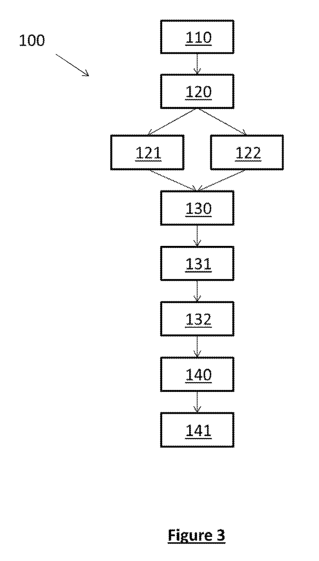
[0039]Referring to FIG. 3 of the drawings, there is provided a schematic illustration of a lens design method 100 according to an embodiment of the present invention, for designing a lens to reshape an actual far-field radiation pattern of a radiation source, such as an antenna or other radiation transmitting device, to a preferred far-field radiation pattern. The lens may be arranged to reshape the radiation pattern by reflecting the radiation in addition to refracting the radiation, and as such, the reshaping of the radiation may be achieved without the radiation passing through the lens. Accordingly, the terms “lens” is understood to comprise a substrate or superstrate, for example, which reflect the radiation, in addition to a more conventional understanding of a lens, in which the radiation passes therethrough. The term lens should therefore be construed as any material which facilitates a reshaping of the radiation pattern.

[0040]The method comprises determining the preferred f...


PUM


Abstract

A lens design method is disclosed for designing a lens to reshape an actual far-field radiation pattern of a radiation source, such as a spiral antenna, to a preferred far-field radiation pattern. The method comprises:—determining a preferred far-field radiation pattern of the radiation source;—deriving a corresponding near-field radiation pattern from the preferred far-field radiation pattern;—determining an actual near-field pattern of the radiation source;—mapping an electric field and a magnetic field of the actual near-field radiation pattern to the derived near-field radiation pattern using a transfer relationship, the transfer relationship comprising material parameters which characterize the lens; and,—determining the material parameters.

Description

RELATED APPLICATIONS[0001]This application is a National Phase application filed under 35 USC § 371 of PCT Application No. PCT / GB2015 / 050788 with an International filing date of Mar. 18, 2015 which claims priority of GB Patent Application 1413125.4 filed Jul. 24, 2014. Each of these applications is herein incorporated by reference in its entirety for all purposes.FIELD OF THE INVENTION[0002]The present invention relates to a lens design method and a radiation source substrate.BACKGROUND OF THE INVENTION[0003]Antennas are well-known for communication and radar systems. Antennas act as a transducer between electromagnetic wave propagation in free space and guided electromagnetic wave propagation in transmission lines. It is possible to design antennas to concentrate the radiated electromagnetic energy in a principal direction and conversely receive electromagnetic energy from a principal direction.[0004]The ability of an antenna to concentrate the transmitted energy in a particular di...

Claims


Application Information

Patent Timeline
IPC IPC(8): H01Q9/04H01Q1/36H01Q19/06H01Q15/00H01Q15/10
CPCH01Q15/10H01Q1/362H01Q19/062H01Q15/0053H01Q15/0046H01Q15/08H01Q19/065H01Q9/27H01Q1/38
Inventor HAO, YANG
Owner BAE SYSTEMS PLC
Why Eureka
Try Eureka