Automation and theater control system

a theater control and automatic technology, applied in the direction of electric controllers, ignition automatic control, instruments, etc., can solve the problems of inability to accommodate, inability to include an antenna for two-way communication with stations, and inability to accommodate home theater controllers

Inactive Publication Date: 2010-07-13
LEGRAND HOME SYST
View PDF343 Cites 184 Cited by
  • Summary
  • Abstract
  • Description
  • Claims
  • Application Information

AI Technical Summary

Problems solved by technology

Of course, an existing home could be re-wired, but this would be cost prohibitive.
The need for separate controllers is primarily due to the fact that previously available devices have not been able to accommodate into one integrated controller the features and functionality necessary to automate a whole house and a home theater due to the unique and specialized nature of each situation.
However, presently available home theater controllers have not included an antenna for two way communication with stations located throughout the house.
In this regard, previously available home theater controllers have been lacking.
It has also been a problem in the past to arrive at a cost effective solution when installing stations for three-way and four way-switches lighting control switches during retrofitting for home automation.
It is often cost prohibitive or at least wasteful to install a standard station with the ability to communicate via RF with a central controller at every wall box for a three-way or four-way switch.
Unsatisfactory solutions to this problem have been attempted, but the result was lacking, in that while a station with limited functionality has been developed, the buttons on these station lack the functionality of the buttons located on a standard station.
In particular, this included not being able to display the status of a load controlled by a station through a status indicator.
Multiple controllers are undesirable due to the increased price and footprints.

Method used


Image

  • Automation and theater control system
  • Automation and theater control system
  • Automation and theater control system

Examples


Embodiment Construction

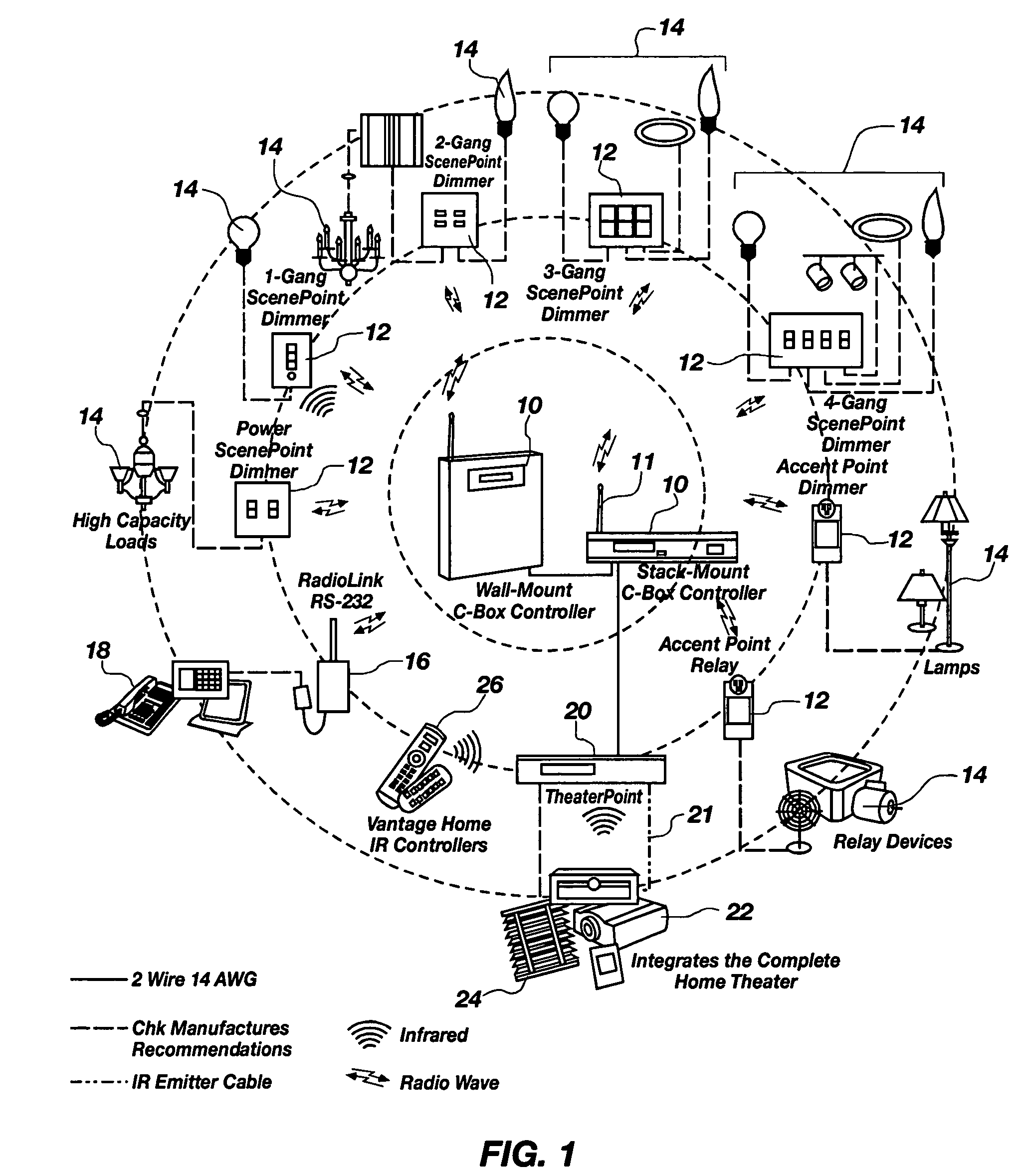
[0041]For the purposes of promoting an understanding of the principles in accordance with the invention, reference will now be made to the embodiments illustrated in the drawings and specific language will be used to describe the same. It will nevertheless be understood that no limitation of the scope of the invention is thereby intended. Any alterations and further modifications of the inventive features illustrated herein, and any additional applications of the principles of the invention as illustrated herein, which would normally occur to one skilled in the relevant art and having possession of this disclosure, are to be considered within the scope of the invention claimed.

[0042]It must be noted that, as used in this specification and the appended claims, the singular forms “a,”“an,” and “the” include plural referents unless the context clearly dictates otherwise. In describing and claiming the present invention, the following terminology will be used in accordance with the defi...


PUM


Abstract

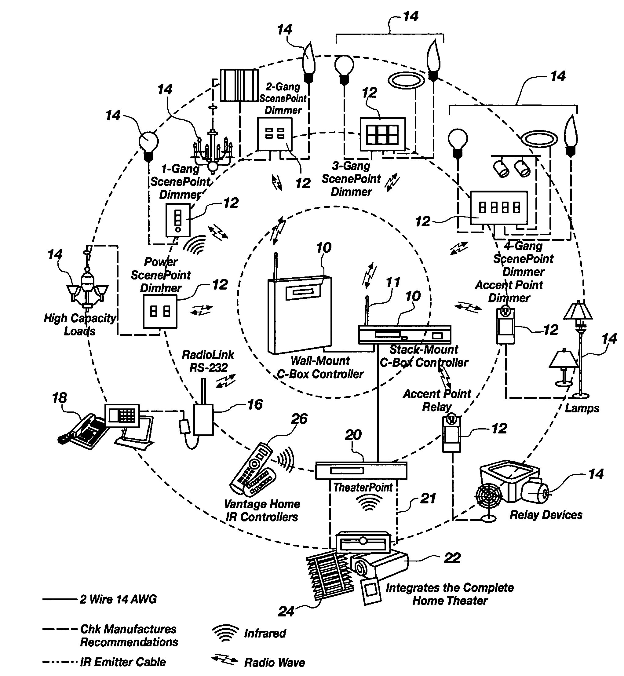
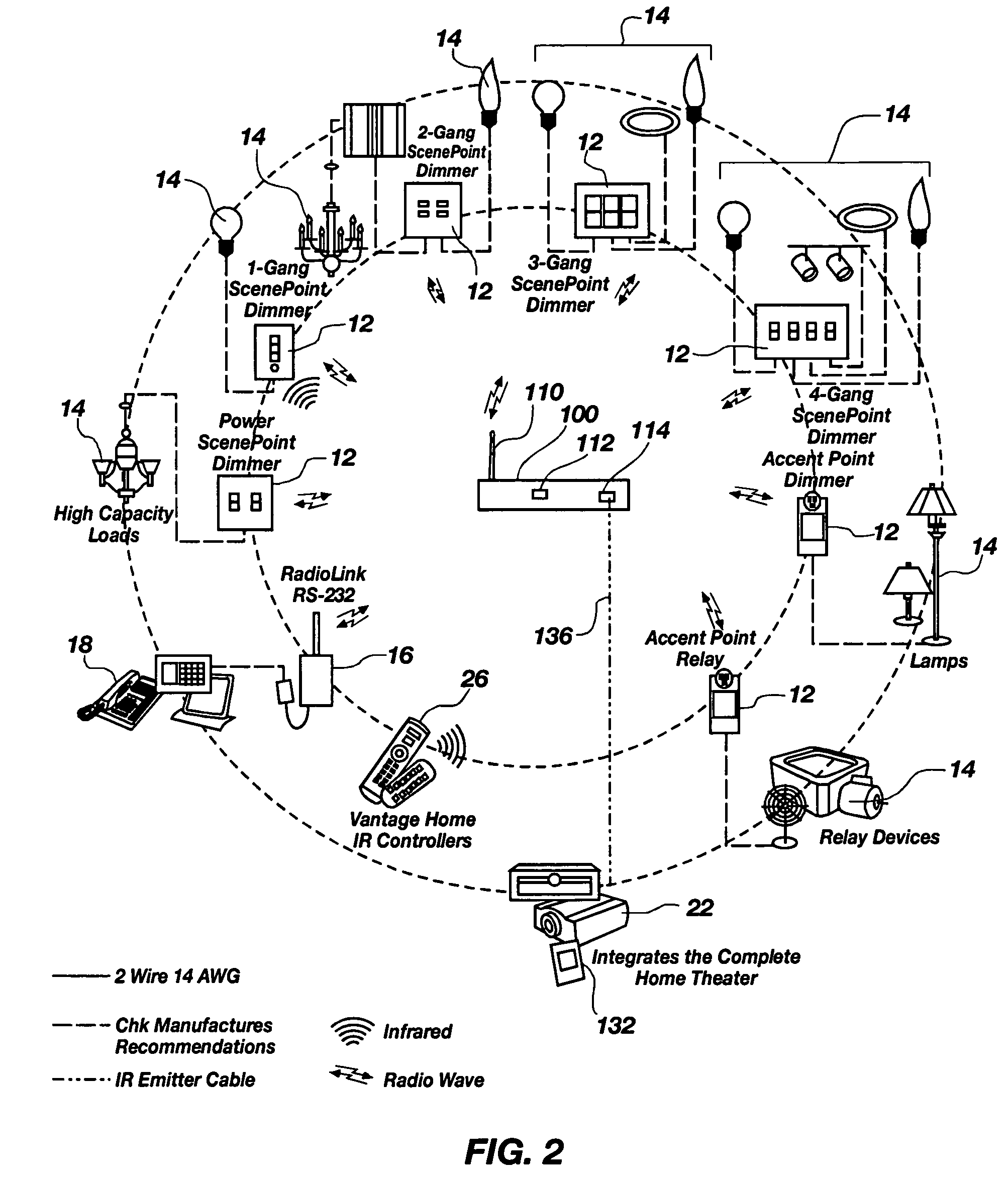
An integrated controller for complete automation with the ability to control electrical devices through both RF transmission and IR transmissions. In one illustrative embodiment, the integrated controller comprises an antenna for two-way communication with stations located throughout a structure. Each station may control the power supply to an attached electrical device. The buttons on the station may control any electrical device on the system through RF transmission with the integrated controller. The integrated controller also may comprise an IR receiver and at least one IR output. The IR receiver may receive signals from a remote and pass them through to a device, such as a device used in a home theater system, with a built in IR receiver via the IR output. In this manner, the integrated controller is capable of providing complete in home automation.

Description

CROSS-REFERENCE TO RELATED APPLICATIONS[0001]This application claims the benefit of U.S. Provisional Application No. 60 / 500,066, filed Sep. 3, 2003, which is hereby incorporated by reference herein in its entirety, including but not limited to those portions that specifically appear hereinafter, the incorporation by reference being made with the following exception: In the event that any portion of the above-referenced provisional application is inconsistent with this application, this application supercedes said above-referenced provisional application.STATEMENT REGARDING FEDERALLY SPONSORED RESEARCH OR DEVELOPMENT[0002]Not Applicable.BACKGROUND[0003]1. The Field of the Invention[0004]The present invention relates generally to building automation systems, and more particularly, but not necessarily entirely, to automation systems for buildings and small theaters.[0005]2. Background Art[0006]Home automation and building automation are fairly new terms. Such terms now refer to combini...

Claims


Application Information

Patent Timeline
Patent Type & Authority Patents(United States)
IPC IPC(8): G08C19/20
CPCG08C17/02G08C23/04G08C2201/40
Inventor CLEGG, PAUL T.MEINERS, JAREDLOSEE, SCOTT C.ALLEN, DOUGLAS E.CHATTERTON, MICHELLELEMKE, JARED T.BEAGLEY, JAMES
Owner LEGRAND HOME SYST
Why Eureka
Try Eureka