Eureka AIR delivers breakthrough ideas for toughest innovation challenges, trusted by R&D personnel around the world.

Fixing device

a fixing device and fixing plate technology, applied in the field of fixing plates, can solve the problems of adverse influence on image quality, lowering peel strength, increasing temperature fall in the end sections compared to the axial central section, etc., and achieves the effects of reducing thermal capacity, reducing glossiness, and increasing temperature fall in the end sections

Inactive Publication Date: 2010-07-13
KONICA MINOLTA BUSINESS TECH INC
View PDF13 Cites 3 Cited by
  • Summary
  • Abstract
  • Description
  • Claims
  • Application Information

AI Technical Summary

Benefits of technology

[0004]However, the reduction in thermal capacity of the fixing roller causes heat discharge from axial end sections of the fixing roller to the outside, and this increases temperature fall in the end sections compared to an axial central section. Consequently, sections of a recording paper sheet which passed the axial end sections of the fixing roller (across-the-width end sections of the sheet) suffer lowered glossiness and lowered peel strength, which causes a problem of adverse influence on image quality.

Problems solved by technology

However, the reduction in thermal capacity of the fixing roller causes heat discharge from axial end sections of the fixing roller to the outside, and this increases temperature fall in the end sections compared to an axial central section.
Consequently, sections of a recording paper sheet which passed the axial end sections of the fixing roller (across-the-width end sections of the sheet) suffer lowered glossiness and lowered peel strength, which causes a problem of adverse influence on image quality.

Method used


Image

  • Fixing device
  • Fixing device
  • Fixing device

Examples


Embodiment Construction

[0078]The invention will hereinbelow be described in detail in conjunction with the embodiments with reference to the accompanying drawings.

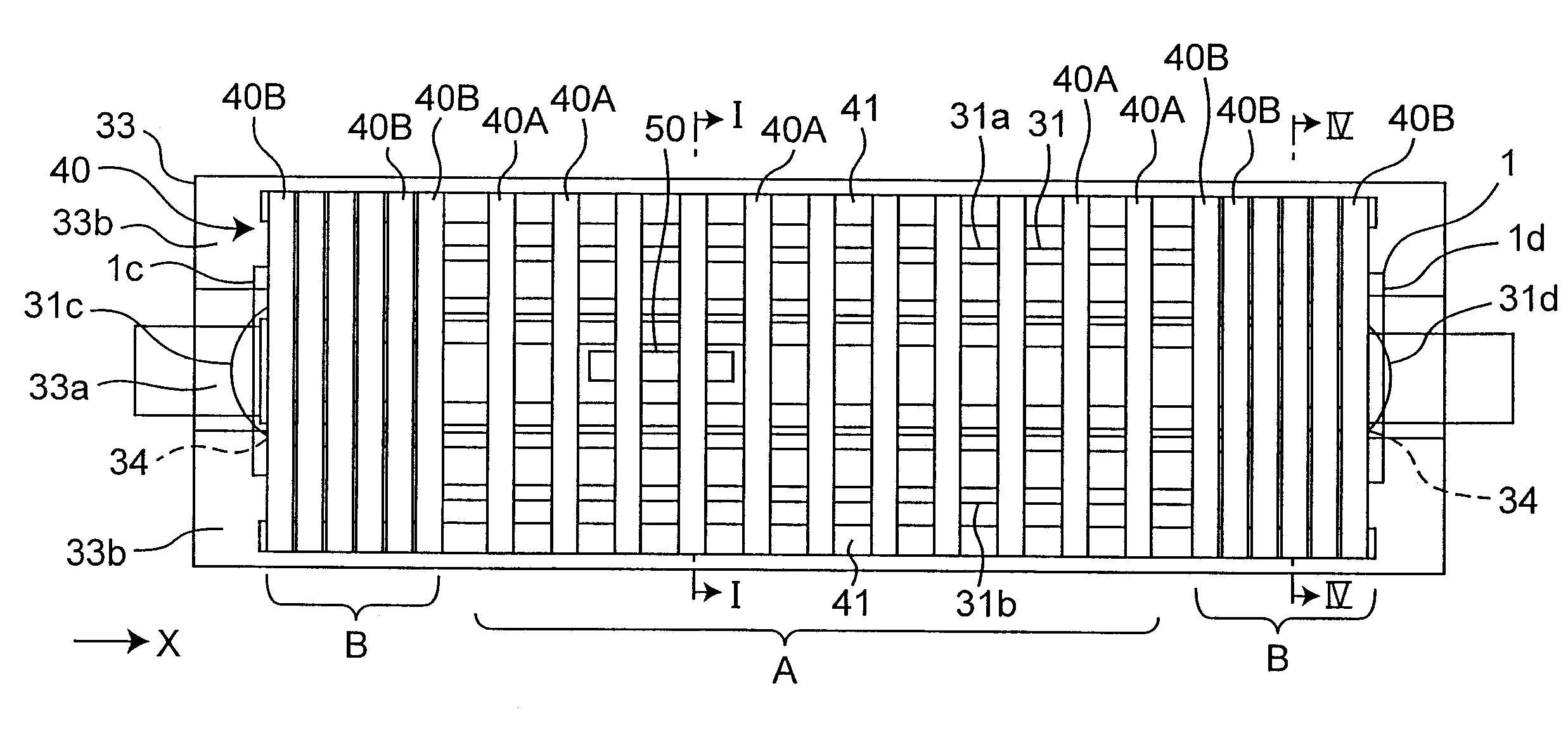
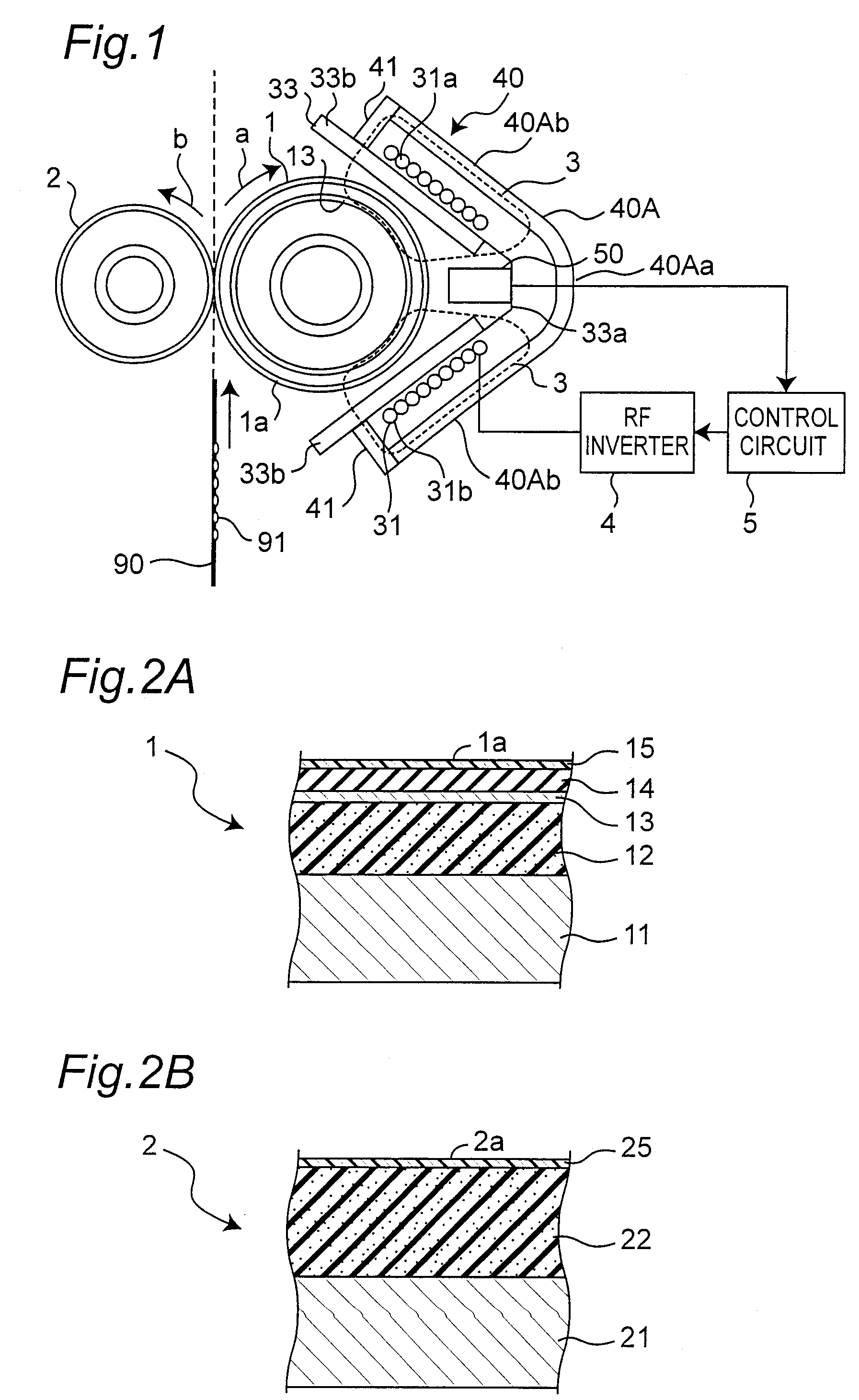
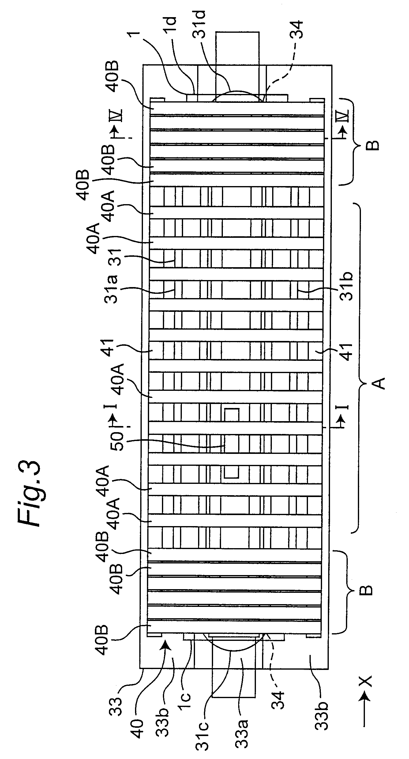
[0079]FIG. 1 shows a cross sectional structure of a fixing device of electromagnetic induction heating method in one embodiment, and FIG. 3 shows the fixing device of FIG. 1, as viewed from the right-hand side (FIG. 1 is equivalent to a cross sectional view taken along an arrow line I-I in FIG. 3). FIG. 4 is a cross sectional view taken along an arrow line IV-IV in FIG. 3. This kind of fixing device is suitable for use in color laser printers and the like.

[0080]As shown in FIG. 1, the fixing device is mainly composed of a fixing roller 1 serving as a fixing member, a pressure roller 2 serving as a pressing member, a coil bobbin 33 serving as a holder, an exciting coil 31, a magnetic substance core 40, an RF inverter 4 and a control circuit 5. Reference numeral 50 denotes a temperature sensor and reference numeral 90 denotes a paper sheet as a sh...


PUM


Abstract

In a fixing device, a magnetic flux generated by a coil passes through a magnetic circuit made of a heat generating layer of a fixing member and a magnetic substance core. The magnetic substance core includes a plurality of main cores each having an elongated form along a circumferential direction of the fixing member and arrayed at intervals along a width direction of a sheet. The end row main cores have a second shape effectively closer to an outer peripheral face of the fixing member compared to a first shape possessed by the central row main cores so as to enhance density of the magnetic flux, which passes the magnetic circuit, more in end sections than in a central section with respect to width direction of the sheet.

Description

[0001]This application is based on an application No. 2006-050104 filed in Japan, the contents of which are hereby incorporated by reference.BACKGROUND OF THE INVENTION[0002]The present invention relates to a fixing device, and more particularly relates to a fixing device of electromagnetic induction heating method. This kind of fixing device is used, for example, as a component of an image forming apparatus such as electrophotographic copiers, printers and facsimiles.[0003]As fixing devices of this kind, as shown in JP 3426229 C, JP 3519401 C and JP 2000-181258 A, there has been known a fixing device having a fixing roller and a pressure roller which are in pressure contact with each other in such a way as to form a nip section for heating a magnetic material layer (such as alloy layers of iron, chrome and nickel; hereinbelow referred to as “heat generating layer”) of the fixing roller by electromagnetic induction, transporting recording paper with a toner image attached thereto th...

Claims


Application Information

Patent Timeline
Patent Type & Authority Patents(United States)
IPC IPC(8): G03G15/20
CPCG03G15/2039G03G15/2007
Inventor OHNO, YASUHIRO
Owner KONICA MINOLTA BUSINESS TECH INC
Why Eureka
Eureka Blog
Learn More