Eureka AIR delivers breakthrough ideas for toughest innovation challenges, trusted by R&D personnel around the world.

Three-dimensional object forming apparatus, three-dimensional object forming method, formation intermediate product, and three-dimensional object

a three-dimensional object and forming apparatus technology, applied in the direction of additive manufacturing processes, manufacturing tools, layer means, etc., can solve the problems of high surface roughness, low positional accuracy of observation, and high surface roughness, so as to achieve high finishing quality and high finishing quality

Inactive Publication Date: 2018-07-19
MIMAKI ENG
View PDF1 Cites 0 Cited by
  • Summary
  • Abstract
  • Description
  • Claims
  • Application Information

AI Technical Summary

Benefits of technology

The patent describes a method and apparatus for creating three-dimensional objects with a smooth outer surface. A roughener is used to create a rough surface texture on the specific area of the object where it will not be covered by a support material. This rough surface texture reduces the difference in surface roughness between the specific area and the contact area, allowing for a more uniform glossiness across the object. This results in a higher quality finished object, regardless of its shape. The roughener preferably roughens the specific area that is not covered with the support material to reduce the likelihood of noticeable surface roughness that may stand out against the surrounding area. Additionally, the method and apparatus reduce the likelihood of the simultaneous contrast effect, which can cause the glossiness of the specific area to appear unnatural, by roughening the adjacent area to create a more uniform surface texture.

Problems solved by technology

Thus, an object formed by the apparatus and the method disclosed in JP2012-96428A1 has a surface with local texture variation, resulting in an observer feeling unnatural.
An area inclined with respect to the work surface is likely to have a low positional accuracy due to gravity or quantization error, and thus is likely to have a large surface roughness.

Method used


Image

  • Three-dimensional object forming apparatus, three-dimensional object forming method, formation intermediate product, and three-dimensional object
  • Three-dimensional object forming apparatus, three-dimensional object forming method, formation intermediate product, and three-dimensional object
  • Three-dimensional object forming apparatus, three-dimensional object forming method, formation intermediate product, and three-dimensional object

Examples


first embodiment

[0050]A three-dimensional object forming apparatus 10A according to a first embodiment will be described below by referring to FIGS. 2 to 7. Electrical block diagram of three-dimensional object forming apparatus 10A

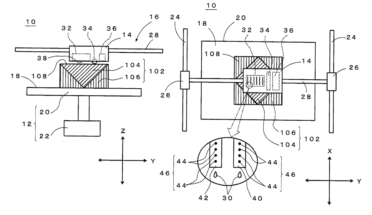
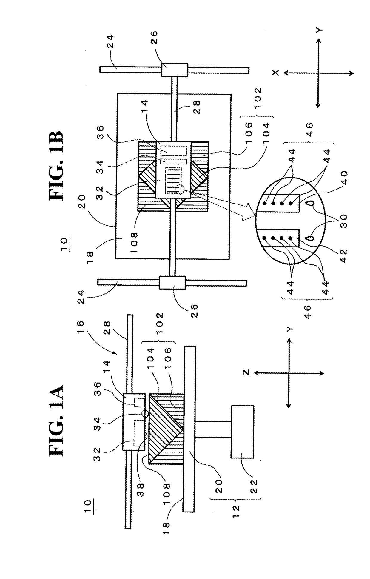
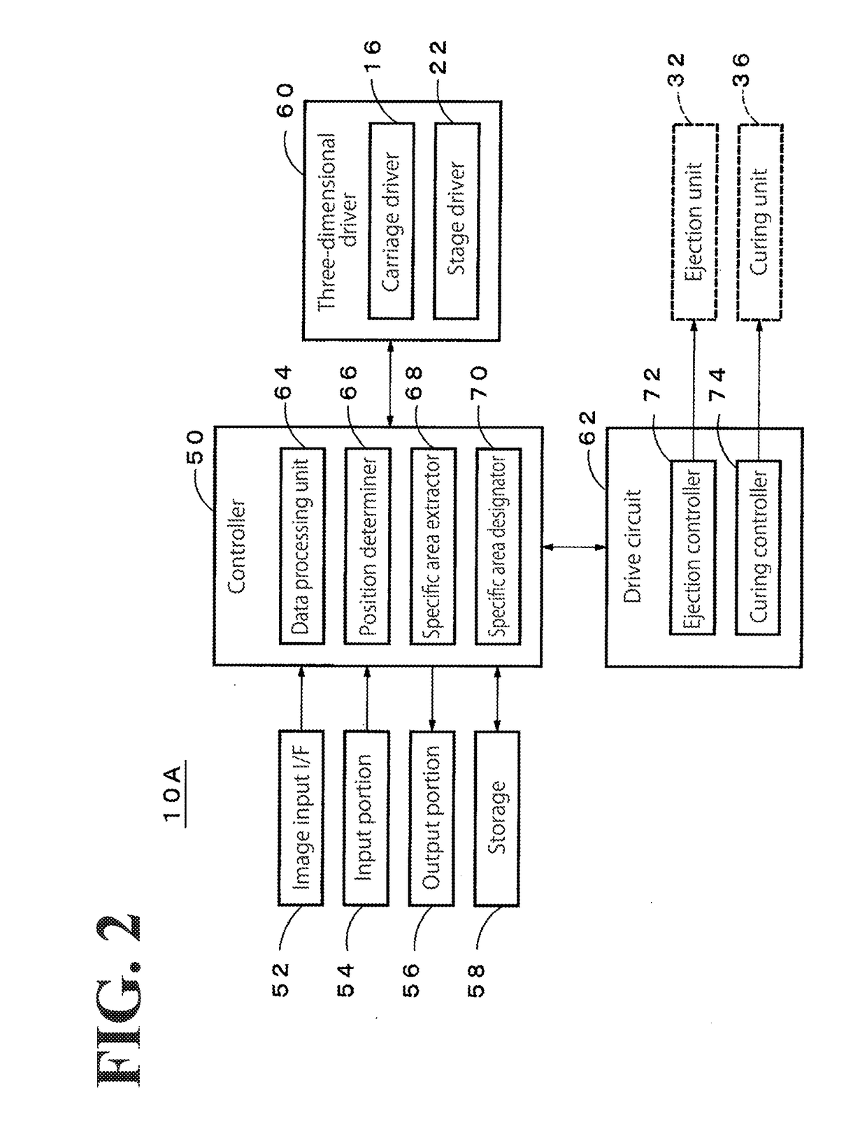
[0051]FIG. 2 is an electrical block diagram of the three-dimensional object forming apparatus 10A according to the first embodiment. The three-dimensional object forming apparatus 10A includes the carriage driver 16, the stage driver 22, the ejection unit 32, and the curing unit 36 illustrated in FIGS. 1A and 1B, and further includes a controller 50, an image input I / F 52, an input portion 54, an output portion 56, a storage 58, a three-dimensional driver 60, and a drive circuit 62.

[0052]The image input I / F 52 is a serial I / F or a parallel I / F, and receives an electrical signal from an external apparatus or device, not illustrated. The electrical signal includes image information about the three-dimensional object 100. The input portion 54 includes a mouse, a keyboard, a ...

second embodiment

[0096]Next, a three-dimensional object forming apparatus 10B according to a second embodiment is described by referring to FIGS. 8 to 10.

Electrical Block Diagram of Three-dimensional Object Forming Apparatus 10B

[0097]FIG. 8 is an electrical block diagram of the three-dimensional object forming apparatus 10B according to the second embodiment. The configuration of the three-dimensional object forming apparatus 10B is different from that in the first embodiment (the controller 50 in FIG. 2) in an operation and a function of a controller 180. Specifically, the controller 180 can read out and execute a program stored in the storage 58 to implement functions including the data processing unit 64, the position determiner 66, the specific area extractor 68, and a data corrector 182 (roughener).

Operation of Three-dimensional Object Forming Apparatus 10B

[0098]Next, an operation of the three-dimensional object forming apparatus 10B illustrated in FIG. 8, that is, an operation of generating th...

third embodiment

[0109]Next, a three-dimensional object forming apparatus 10C according to a third embodiment will be described below by referring to FIGS. 11 to 13. Electrical Block Diagram of Three-dimensional Object Forming Apparatus 10C

[0110]FIG. 11 is an electrical block diagram of the three-dimensional object forming apparatus 10C according to the third embodiment. The configuration of the three-dimensional object forming apparatus 10C is different from that in the first embodiment (the controller 50 in FIG. 2) in an operation and a function of a controller 200. Specifically, the controller 200 can read out and execute a program stored in the storage 58 to implement functions including the data processing unit 64, the position determiner 66, the specific area extractor 68, and a position corrector 202 (roughener).

Operation of Three-Dimensional Object Forming Apparatus 10C

[0111]Next, an operation of the three-dimensional object forming apparatus 10C illustrated in FIG. 11, and in particular, an...


PUM

PropertyMeasurementUnit
Densityaaaaaaaaaa
Areaaaaaaaaaaa

Abstract

A three-dimensional-object forming apparatus generates a three-dimensional object such that from a formation intermediate product obtained by sequentially depositing unit layers each including a build material and / or a support material on a work surface, a support made of the support material is removed. The three-dimensional-object forming apparatus includes a position determiner and a roughener. The position determiner determines a position of the build material and a position of the support material to make a partial surface contact between the three-dimensional object and the support. The roughener roughens a specific area defined by an outer surface among outer surfaces of the build material located at the position determined by the position determiner. The outer surface is parallel with the work surface.

Description

CROSS-REFERENCE TO RELATED APPLICATIONS[0001]The present application claims priority under 35 U.S.C. § 119 to Japanese Patent Application No. 2017-006080, filed Jan. 17, 2017. The contents of this application are incorporated herein by reference in their entirety.BACKGROUNDField of the Invention[0002]The present disclosure relates to a three-dimensional object forming apparatus and a three-dimensional object forming method. The present disclosure also relates to a formation intermediate product and a three-dimensional object formed by this method.Discussion of the Background[0003]Some recently developed three-dimensional object forming apparatuses (what are known as 3D printers) form a three-dimensional object by solidifying and sequentially depositing unit layers along a vertical direction. The apparatuses use a “build material” for forming an object and a “support material” for maintaining the shape of the object to form a formation intermediate product. Then, the support material...

Claims


Application Information

Patent Timeline
IPC IPC(8): B29C64/194B29C64/227B29C64/112B29C64/393B29C64/205B33Y10/00B33Y30/00
CPCB29C64/194B29C64/112B29C64/205B29C64/227B29C64/393B33Y10/00B33Y30/00B29K2995/0072B29K2995/0022B33Y50/02B29C64/40B33Y40/20
Inventor OCHI, KAZUHIRO
Owner MIMAKI ENG
Why Eureka
Eureka Blog
Learn More