Composite machining tool

a technology of composite materials and machining tools, which is applied in the direction of manufacturing tools, grinding devices, transportation and packaging, etc., can solve the problems of difficult cutting of pmc materials, present difficulties in part manufacture, and difficult elastic modulus and physical structure of pmc materials

Active Publication Date: 2018-12-20
NORTHUMBRIA UNIVERSITY
View PDF0 Cites 1 Cited by
  • Summary
  • Abstract
  • Description
  • Claims
  • Application Information

AI Technical Summary

Benefits of technology

[0020]Optionally, the method further comprises the step of rotating the composite material about its axis to effect the machining action.

Problems solved by technology

The high strength, high elastic modulus and physical structure of PMC materials, while vital to their application, do present difficulties during part manufacture.
When subjected to machining with existing tools, PMC materials are often found to be difficult to cut, abrasive to tooling and susceptible to delamination and splintering.
This leads to part irregularity and poor finish quality which is unacceptable in many of the most demanding applications.
This reduces the speed of manufacture and cost effectiveness of PMC materials and is a barrier to their wider use.
This approach has been found to be unsatisfactory because the presence of an abrasive on a cutting region of the tool prevents the cutting action from being performed properly and can potentially cause high levels of tool wear.

Method used


Image

  • Composite machining tool
  • Composite machining tool
  • Composite machining tool

Examples


Embodiment Construction

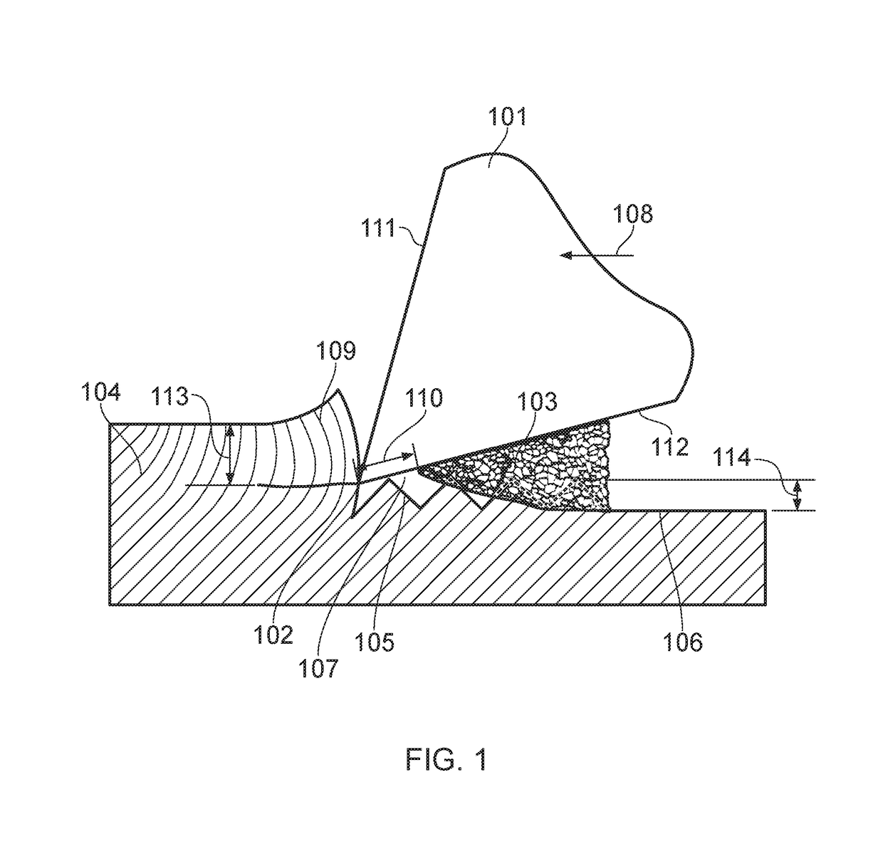
[0032]FIG. 1 provides a schematic diagram illustrating a section of composite material in the process of machining in accordance with certain embodiments of the invention. The types of materials that can be machined by the invention include Polymer Matrix Composite (PMC) materials such as carbon-fibre and glass-fibre reinforced polymer composites, and so on. These materials will be referred to henceforth as composite materials.

[0033]The tool body 101 comprises a cutting edge 102 and a grinding region 103. The cutting edge 102 is formed at the intersection between a first and second surface 111,112 of the tool body 101. The grinding region 103 is located on the second surface 112 of the tool body 101 and is adjacent to the cutting edge 102. The second surface 112 is commonly known as the clearance surface. The grinding region 103 is characterised in that it is abrasive to composite materials. The cutting edge 102 and grinding region 103 are positioned on the tool body 101 such that a...


PUM

PropertyMeasurementUnit
lengthaaaaaaaaaa
lengthaaaaaaaaaa
depthaaaaaaaaaa

Abstract

A composite machining tool includes a tool body with at least one cutting edge and at least one grinding region. The grinding region is located adjacent to the cutting edge such that there is a gap between the grinding region and the cutting edge and such that when the tool performs a machining action the cutting edge and the grinding region act together on a material surface.

Description

TECHNICAL FIELD[0001]This invention relates to the field of composite machining tools.BACKGROUND[0002]Polymer Matrix Composite (PMC) materials have become increasingly important in many demanding fields of engineering. PMCs are typically made up of a matrix component—a polymer-based resin, and a reinforcing component—a fibre such as carbon, glass or aramid. It is by combining the complementary mechanical properties of these two components that PMCs can be engineered to suit a wide range of applications. Well known PMC materials are carbon-fibre and glass-fibre reinforced polymer composites, although many other types are in use.[0003]The structure of PMC materials means that they can exhibit a very high strength-to-weight ratio and elastic modulus. This makes them particularly suitable for application in industries where strength and weight are key considerations, such as aerospace, automotive, sports equipment and renewable energy. Many of the industries that use PMCs also demand pa...

Claims


Application Information

Patent Timeline
Patent Type & Authority Applications(United States)
IPC IPC(8): B23B27/02B23B51/08B23C5/04B23P23/02B24B1/00B24D5/02B24D5/12
CPCB23B27/02B23B51/08B23C5/04B23P23/02B24B1/00B24D5/02B24D5/12B24D5/14B24D18/0018B24D99/005B23B2226/27B23C5/00B23B27/00B23C2226/27
Inventor SHYHA, ISLAM
Owner NORTHUMBRIA UNIVERSITY
Why Eureka
Try Eureka