Bicycle gear shifter

a gear shifter and bicycle technology, applied in bicycle equipment, mechanical equipment, transportation and packaging, etc., can solve the problems of increasing the force required to operate the gear shifter, the inner wire that cannot be arranged inside the gear shifter is limited, and the inner wire cannot reach the gear changing device, so as to improve the degree of design freedom

Inactive Publication Date: 2010-07-20
SHIMANO INC
View PDF11 Cites 13 Cited by
  • Summary
  • Abstract
  • Description
  • Claims
  • Application Information

AI Technical Summary

Benefits of technology

[0013]One object of the present invention is to improve a degree of design freedom with respect to gear shifters having gear shift cables connected thereto. A bicycle gear shifter in accordance with a first aspect of the present invention basically comprises a mounting part, a connector guide part, a winding member, an operating member, an inner wire connector and a connecting cable. The mounting part includes a handlebar mounting structure with a handlebar mounting axis and a wire guiding structure extending from the handlebar mounting structure. The wire guiding structure includes a wire movement space extending to an outer casing stop. The connector guide part is disposed inside the wire movement space of the wire guiding structure. The winding member is movably connected to the mounting part. The operating member operatively connected to the winding member to move the winding member relative to the mounting part. The inner wire connector movably arranged inside the wire movement space along the connector guide part. The inner wire connector is configured to detachably hold an end of an inner wire of a gear shift cable. The connecting cable includes a first end connected to the winding member and a second end connected to the inner wire connector such that the inner wire connector moves in response to movement of the winding member.
[0014]With this gear shifter, the tip end of the inner wire of the gear shift cable is held by the inner wire holding part of the inner wire connector. The inner wire connector is connected to the second end of the connecting cable, the first end of which is connected to the winding member. The inner wire connector moves along the connector guide part provided inside the wire guiding structure in response to turning movement of the winding member. The inner wire is connected to the winding member through the connecting cable, and the inner wire connector is guided by the connector guide part in such a manner that it can move smoothly. If the connector guide part is configured such that the movement direction of the inner wire connector can be changed, then the movement direction of the cable spanning from the inner wire to the winding member through the connecting cable can be changed easily. Since a connecting cable is provided between the winding member and the inner wire and the inner wire connector that holds the inner wire is guided by the connector guide part, the length of the inner wire is less limited and the mounting direction of the gear shift cable is less limited. As a result, there are fewer constrictions on the shape and structure of the gear shifter and the degree of design freedom of the gear shifter is improved.
[0017]A bicycle gear shifter in accordance with a fourth aspect of the present invention is a bicycle gear shifter in accordance with any one of the first to third aspects, wherein the inner wire connector is fixed to the second end of the connecting cable in a non-reattachable connection. With this aspect of the invention, the inner wire connector is fixed to the second end of the connecting cable by welding, crimping, or other suitable method. As a result, the work associated with connecting the inner wire connector to the connecting cable can be eliminated.
[0018]With the present invention, since a connecting cable is provided between the winding member and the inner wire and the inner wire connector that holds the inner wire is guided by the connector guide part, the length of the inner wire is less limited and the mounting direction of the gear shift cable is less limited. As a result, there are fewer constrictions on the shape and structure of the gear shifter and the degree of design freedom of the gear shifter is improved.

Problems solved by technology

In the conventional configuration just described, since the length of the inner wire is predetermined, there is the possibility that the inner wire will not reach the gear changing device if the length of the portion of the inner wire that is arranged inside the gear shifter between the outer casing stop and the place where the inner wire is attached to the winding member is too long.
Therefore, the length of inner wire that can be arranged inside the gear shifter is limited.
Thus, this can result in an increase in the force required to operate the gear shifter.
Consequently, the mounting direction of the gear shift cable is also limited.
Since the length of the portion of the inner wire arranged inside the gear shifter and the mounting direction of the gear shift cable are limited, there are constraints on the shape and structure of the gear shifter and the degree of design freedom with respect to the gear shifter is low.

Method used


Image

  • Bicycle gear shifter
  • Bicycle gear shifter
  • Bicycle gear shifter

Examples


Embodiment Construction

[0028]Selected embodiments of the present invention will now be explained with reference to the drawings. It will be apparent to those skilled in the art from this disclosure that the following descriptions of the embodiments of the present invention are provided for illustration only and not for the purpose of limiting the invention as defined by the appended claims and their equivalents.

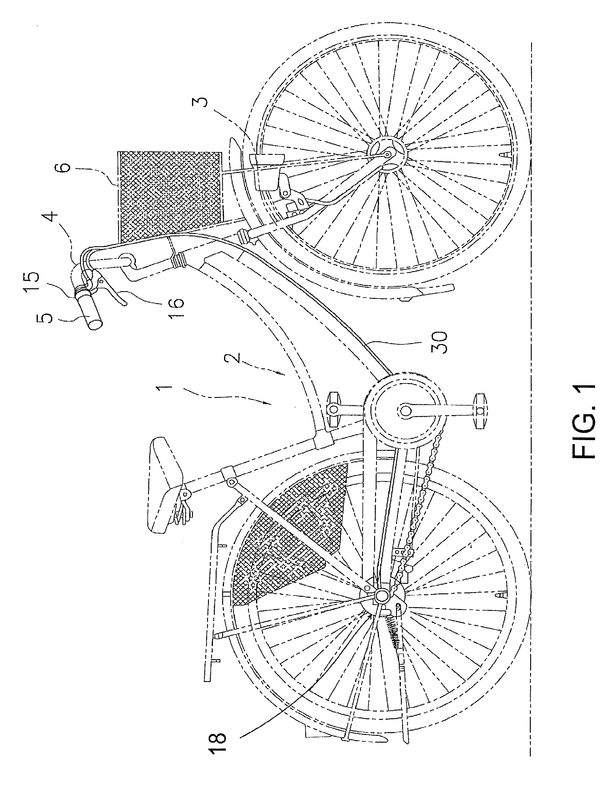
[0029]Referring initially to FIG. 1, a bicycle 1 is illustrated in accordance with a first embodiment of the present invention. The bicycle 1 includes a frame 2, a front fork 3, and a handlebar 4. The handlebar 4 is attached to the frame2 in such a manner as to be fixed to an upper portion of the front fork 3. A front basket 6 is attached to the front of the frame 2. A grip-type gear shifter 15 is mounted to the handlebar 4. A brake operating device 16 is arranged on the handlebar 4 on the inward side of the gear shifter 15. An internally-geared hub 18 is mounted to a rear end portion of the frame ...


PUM


Abstract

A bicycle gear shifter is provided with a mounting part, a connector guide part, a winding member, an operating member, an inner wire connector and a connecting cable. The mounting part includes a handlebar mounting structure and a wire guiding structure extending from the handlebar mounting structure. The wire guiding structure includes a wire movement space extending to an outer casing stop with the connector guide part disposed therein. The inner wire connector moves inside the wire movement space along the connector guide part. The inner wire connector detachably holds an end of an inner wire of a gear shift cable. The connecting cable is connected to the winding member and the inner wire connector to move the inner wire connector in response to movement of the winding member.

Description

CROSS-REFERENCE TO RELATED APPLICATIONS[0001]This application claims priority under 35 U.S.C. §119 to Japanese Patent Application No. 2006-305270, filed Nov. 10, 2006. The entire disclosure of Japanese Patent Application No. 2006-305270 is hereby incorporated herein by reference.BACKGROUND OF THE INVENTION[0002]1. Field of the Invention[0003]This invention generally relates to a gear shifter. More particularly, the present invention relates to a bicycle gear shifter that is capable of being mounted to a handlebar of a bicycle.[0004]2. Background Information[0005]Bicycling is becoming an increasingly more popular form of recreation as well as a means of transportation. Moreover, bicycling has become a very popular competitive sport for both amateurs and professionals. Whether the bicycle is used for recreation, transportation or competition, the bicycle industry is constantly improving the various components of the bicycle. Over the years, the bicycle gear shifters have been extensiv...

Claims


Application Information

Patent Timeline
Patent Type & Authority Patents(United States)
IPC IPC(8): F16C1/22
CPCB62K23/04B62M25/04Y10T74/20438Y10T74/20462
Inventor OKAMOTO, TATSUSHI
Owner SHIMANO INC
Why Eureka
Try Eureka