Dual track ladder with brake mechanism that is automatically applied to the upper tracks to hold the ladder in place during use

a double-track, automatic application technology, applied in mechanical devices, building scaffolds, building aids, etc., can solve the problems of ladder now completely immobilized

Active Publication Date: 2010-07-20
MATERIAL CONTROL
View PDF15 Cites 29 Cited by
  • Summary
  • Abstract
  • Description
  • Claims
  • Application Information

AI Technical Summary

Benefits of technology

[0004]The dual track ladder of the present invention incorporates brake mechanisms that are applied automatically to each of the upper tracks by a person on the ladder to hold the ladder in place during use and a separate lateral brake mechanism that is applied by spring tension to the lateral track or rod to hold the ladder in one position on the transverse track until the lateral brake is manually deactivated. Such mechanisms work in conjunction with the spring-loaded casters and rubber pads at the lower end of the ladder. When the ladder is in use, the lateral brake is applied automatically by spring tension, and the weight of the user is thereafter sufficient to compress the spring-loaded casters and lock the base of the ladder to the floor. As the worker progresses up the ladder, whether provided with or without a platform, the weight of the worker automatically applies the brake mechanisms to the upper tracks to hold the ladder in place during use and to prevent the ladder from moving either intentionally or mistakenly forward. The final result is that the ladder is now completely immobilized. Thus, the user can no longer inch the ladder forward hence the wheels of the carriage system on the dual tracks at the top of the ladder are now restrained and prevented from jerking forward, either intentionally or mistakeningly forward.

Problems solved by technology

The final result is that the ladder is now completely immobilized.

Method used


Image

  • Dual track ladder with brake mechanism that is automatically applied to the upper tracks to hold the ladder in place during use
  • Dual track ladder with brake mechanism that is automatically applied to the upper tracks to hold the ladder in place during use
  • Dual track ladder with brake mechanism that is automatically applied to the upper tracks to hold the ladder in place during use

Examples


Embodiment Construction

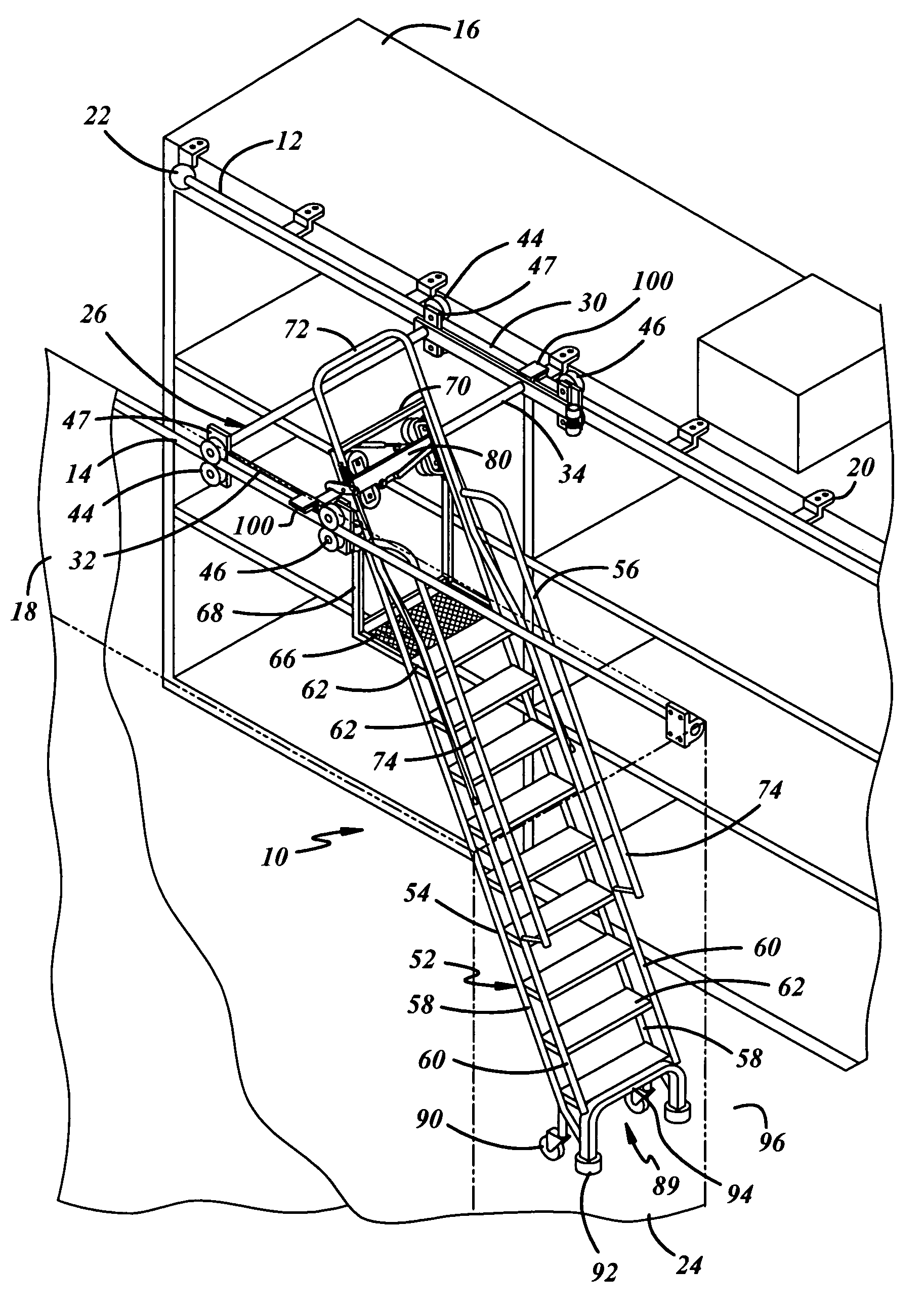
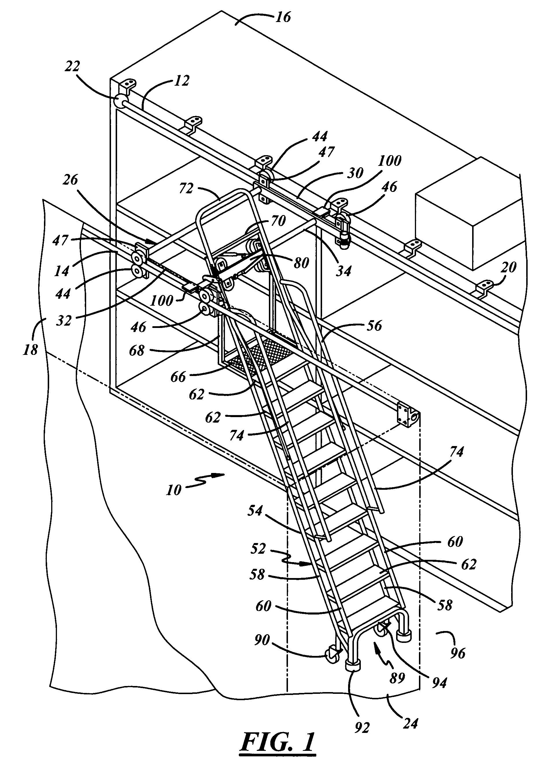
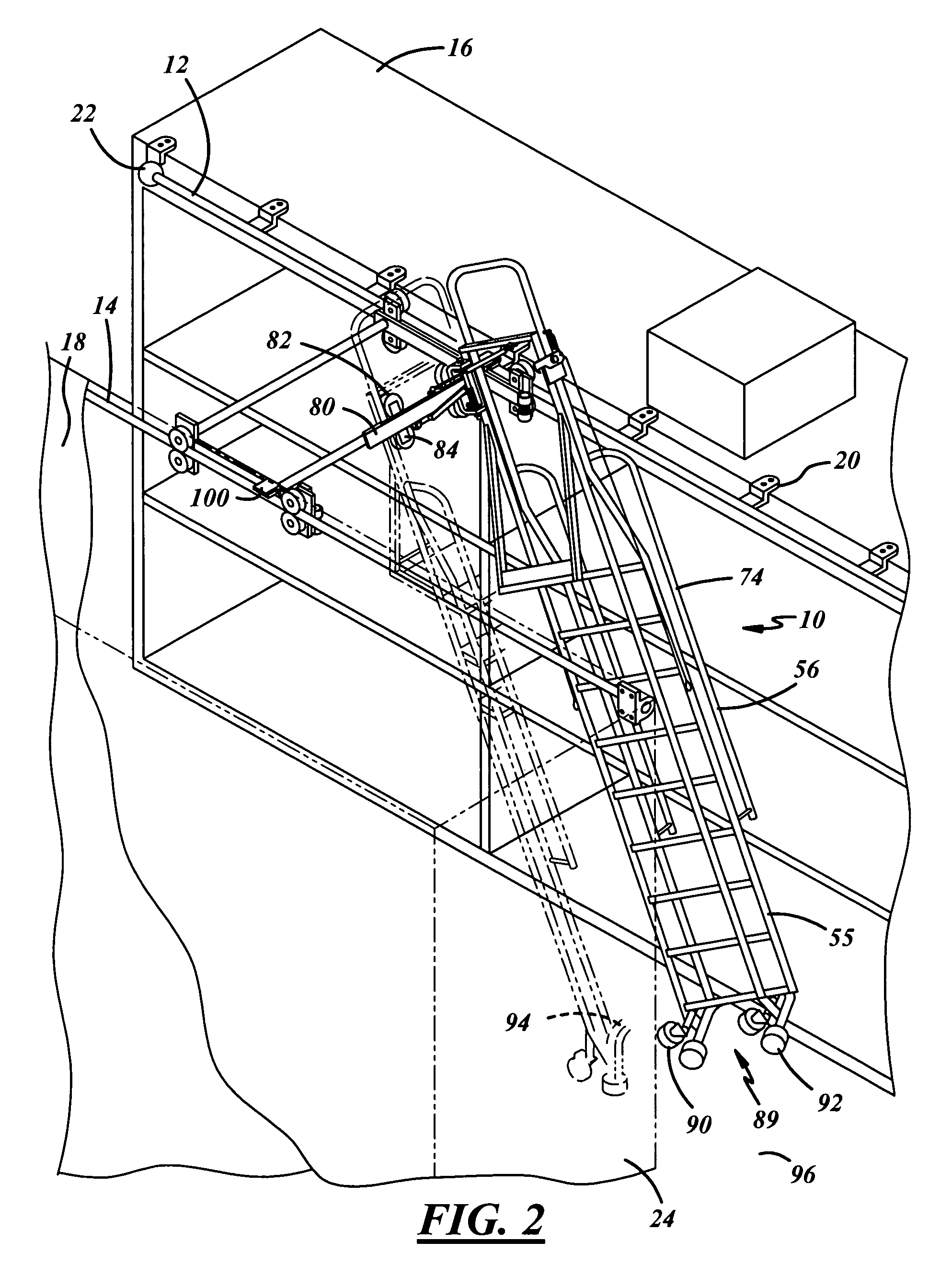
[0032]FIGS. 1 and 2 illustrate the ladder system 10 which includes a pair of dual tracks or rails including a first overhead guide track 12 and a second overhead guide track 14. The dual tracks 12 and 14 are mounted at the top of a pair of longitudinally extending, laterally spaced apart storage shelves 16 and 18. The dual tracks 12 and 14 are mounted on the front surface or side of the storage shelves 16 and 18 by means of a plurality of longitudinally spaced brackets 20 or end mounts 22. The storage shelves 16 and 18 are mounted on the floor 96 of a building, store or warehouse, with the space between the shelves 16 and 18 defining an aisle or aisle way 24.

[0033]As used herein, the term “longitudinal direction” is defined as extending parallel to the laterally spaced apart storage shelves 16 and 18. The term “lateral direction” is defined as extending laterally between the storage shelves 16 and 18.

[0034]The track system 10 includes an overhead roller carriage or roller structure ...


PUM


Abstract

The ladder system is disposed between two spaced storage shelves of the types found in crowded warehouses. The ladder is mounted on overhead guide tracks and may be moved longitudinally along the shelves and laterally between the shelves. Locating means are provided for immobilizing the ladder against movement laterally and longitudinally. The locating means includes a pair of spring-loaded casters and rubber pads at the lower end of the ladder and a pair of braking mechanisms overlying and engageable with the guide tracks when subjected to the weight of the user to prevent movement of the ladder at the top thereof either intentionally or unintentionally. Finally, a lateral brake is carried by the ladder which prevents the roller carriage from moving laterally. The brake is applied when the ladder is in use.

Description

BACKGROUND OF THE INVENTION[0001]This application relates to a ladder system used between a pair of laterally spaced apart storage shelves located in a store or warehouse. My prior U.S. Pat. Nos. 5,413,191, issued May 9, 1995, entitled “Dual Track Ladder” and U.S. Pat. No. 6,619,427, issued Sep. 16, 2003, entitled “Foldable Dual Track Ladder” disclose ladder systems which have been commercially successful. The existing dual track ladders have spring-loaded casters and rubber pads at the lower end of the ladder. When the ladder is in use, the weight of the user or worker is sufficient to compress the caster springs and urge the rubber pads against the floor to thereby lock, secure or immobilize the base of the ladder on the floor.[0002]However, with taller ladders and especially ladders provided with a platform for the user or worker at the top of the ladder, some have found that the construction of the ladder permitted movement of the upper part of the ladder longitudinally parallel...

Claims


Application Information

Patent Timeline
Patent Type & Authority Patents(United States)
IPC IPC(8): E04G1/36
CPCE06C1/397E06C9/12E06C7/183E06C7/182
Inventor KERR, JAMES F.
Owner MATERIAL CONTROL
Why Eureka
Try Eureka